Epson 9600 Service Manual - Page 213
Main Board Adjustment
 |
UPC - 010343841888
View all Epson 9600 manuals
Add to My Manuals
Save this manual to your list of manuals |
Page 213 highlights
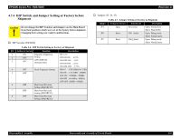
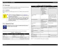
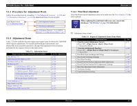
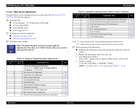
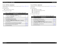
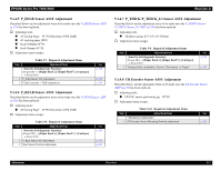
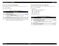
EPSON Stylus Pro 7600/9600 5.1.4.2 Main Board Adjustment Described below are the adjustment items to be made once the MAIN Board (C472 MAIN) (p.207) has been replaced. † Adjusting tools: „ A3Tracing Paper #F751(Microtrace #300 LMB) „ A3 Copy Paper (PPC) „ Scale 1000mm #F713 „ Scale Stopper #F714 † Work operations before adjustment: „ Parameter Backup (p.218) „ Firmware Reinstallation (p.219) † Adjustment items (steps): CHECK P O IN T When "Parameter Backup" has been executed, make the adjustment by Procedure A in Table 5-4 below; there is no need of following Procedure B. Table 5-4. Required Adjustment Items (Main Circuit) Procedure Procedure A*1 B*2 Adjustment Item (Power OFF → [Paper Feed ∆]+[Paper Feed ∇] +[Cut/Eject] → Power ON) 1 1 Rear Sensor AD Adjustment 2 2 Edge Sensor AD Adjustment 3 Initial Charge Flag Clear 4 Head Rank ID Checking 5 Head Rank Input 6 Head Nozzle Checking (Cleaning) 7 Head Slant Checking 8 Feed Correction + T&B Adjustment 9 Rear Sensor Position Adjustment 10 Platen Position Adjustment (Flash Point Adjustment) See p. 220 p. 231 p. 232 p. 257 - p. 233 p. 237 p. 246 p. 239 p. 243 p. 244 Revision A Table 5-4. Required Adjustment Items (Main Circuit) (continued) Procedure Procedure A*1 B*2 Adjustment Item See 11 Round Trip Print Position Adjustment (Bi-D Adjustment) p.248 12 Round Trip Print Position (Bi-D Adjustment) Checking p.252 13 Head Gap Adjustment (Uni-D Adjustment) p. 253 14 USB ID Input 3 15 RTC writing initialization 16 Power Cleaning 17 Head Nozzle Checking (Cleaning) 18 Test Pattern Printing p. 273 p. 71 p. 259 p. 237 p. 255 Note "*1": Adjustment procedure when parameter backup has been executed "*2": Adjustment procedure when parameter backup can not be executed † Work operations after adjustment: „ Replacing the maintenance tank and resetting the maintenance tank life counter 1. Replace the maintenance tank with a new one. 2. Start Maintenance Mode 2. (Power OFF →[Paper Source]+[Eject]+[Paper Feed] → Power ON) 3. Clear the counter. ("CLEAR COUNTERS"→"MAINTE. TANK") NOTE: For details, refer to "1.4.5 Maintenance Mode 2" (p.70). Adjustment Overview 213
-
 1
1 -
2
-
3
-
4
-
5
-
6
-
7
-
8
-
9
-
10
-
11
-
12
-
13
-
14
-
15
-
16
-
17
-
18
-
19
-
20
-
21
-
22
-
23
-
24
-
25
-
26
-
27
-
28
-
29
-
30
-
31
-
32
-
33
-
34
-
35
-
36
-
37
-
38
-
39
-
40
-
41
-
42
-
43
-
44
-
45
-
46
-
47
-
48
-
49
-
50
-
51
-
52
-
53
-
54
-
55
-
56
-
57
-
58
-
59
-
60
-
61
-
62
-
63
-
64
-
65
-
66
-
67
-
68
-
69
-
70
-
71
-
72
-
73
-
74
-
75
-
76
-
77
-
78
-
79
-
80
-
81
-
82
-
83
-
84
-
85
-
86
-
87
-
88
-
89
-
90
-
91
-
92
-
93
-
94
-
95
-
96
-
97
-
98
-
99
-
100
-
101
-
102
-
103
-
104
-
105
-
106
-
107
-
108
-
109
-
110
-
111
-
112
-
113
-
114
-
115
-
116
-
117
-
118
-
119
-
120
-
121
-
122
-
123
-
124
-
125
-
126
-
127
-
128
-
129
-
130
-
131
-
132
-
133
-
134
-
135
-
136
-
137
-
138
-
139
-
140
-
141
-
142
-
143
-
144
-
145
-
146
-
147
-
148
-
149
-
150
-
151
-
152
-
153
-
154
-
155
-
156
-
157
-
158
-
159
-
160
-
161
-
162
-
163
-
164
-
165
-
166
-
167
-
168
-
169
-
170
-
171
-
172
-
173
-
174
-
175
-
176
-
177
-
178
-
179
-
180
-
181
-
182
-
183
-
184
-
185
-
186
-
187
-
188
-
189
-
190
-
191
-
192
-
193
-
194
-
195
-
196
-
197
-
198
-
199
-
200
-
201
-
202
-
203
-
204
-
205
-
206
-
207
-
 208
208 -
 209
209 -
 210
210 -
 211
211 -
 212
212 -
 213
213 -
 214
214 -
 215
215 -
 216
216 -
 217
217 -
 218
218 -
219
-
220
-
221
-
222
-
223
-
224
-
225
-
226
-
227
-
228
-
229
-
230
-
231
-
232
-
233
-
234
-
235
-
236
-
237
-
238
-
239
-
240
-
241
-
242
-
243
-
244
-
245
-
246
-
247
-
248
-
249
-
250
-
251
-
252
-
253
-
254
-
255
-
256
-
257
-
258
-
259
-
260
-
261
-
262
-
263
-
264
-
265
-
266
-
267
-
268
-
269
-
270
-
271
-
272
-
273
-
274
-
275
-
276
-
277
-
278
-
279
-
280
-
281
-
282
-
283
-
284
-
285
-
286
-
287
-
288
-
289
-
290
-
291
-
292
-
293
-
294
-
295
-
296
-
297
-
298
-
299
-
300
-
301
-
302
-
303
-
304
-
305
-
306
-
307
-
308
-
309
-
310
-
311
-
312
-
313
-
314
-
315
-
316
-
317
-
318
-
319
-
320
-
321
-
322
-
323
-
324
-
325
-
326
-
327
-
328
-
329
-
330
-
331
-
332
-
333
-
334
-
335
-
336
 |
 |
