Epson 9600 Service Manual - Page 170
Front Cover Support Removal
 |
UPC - 010343841888
View all Epson 9600 manuals
Add to My Manuals
Save this manual to your list of manuals |
Page 170 highlights
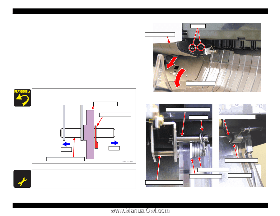
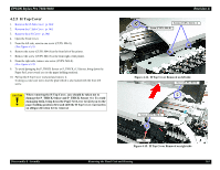
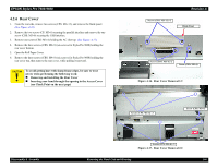
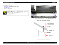
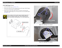
EPSON Stylus Pro 7600/9600 4.2.9 Front Cover 1. Open the Front Cover. 2. Push in the two hooks to the left of the cover and remove the Front Cover Support. (See Figure 4-22) 3. Release the Front Cover Spring L from the Front Cover Spring Catch Shaft on the left side of the Front Cover. (See Figure 4-23) 4. Remove the Plastic Stop Wheel E5 on the left side of the Front Cover and move the Front Cover Fulcrum Pin outward for its removal. 5. Release the Front Cover Spring R from the Front Cover Spring Catch Shaft on the right side of the Front Cover. 6. Remove the Front Cover from the Front Cover Fulcrum Pin R. Install the Plastic Stop Wheels in the correct orientations, respectively. Front Cover Plastic Stop Wheel E5 Front Cover Support Hooks Revision A Front Cover Figure 4-22. Front Cover Support Removal Front Cover Spring Catch Shaft E-ring Front Cover Fulcrum Pin R Long Front Cover Fulcrum Pin L Short A D JU S TM E N T R E Q U IR E D The cover switch holder installation position should be checked so that the cover sensor ASSY is linked to the front cover when it opens and closes. Refer to "5.1.4.9 Cover Sensor ASSY Adjustment" (p.216) Front Cover Spring R Front Cover Fulcrum Pin L Front Cover Spring L Plastic Stop Wheel E Front Cover Figure 4-23. Front Cover Removal Disassembly & Assembly Removing the Panel Unit and Housing 170
-
 1
1 -
2
-
3
-
4
-
5
-
6
-
7
-
8
-
9
-
10
-
11
-
12
-
13
-
14
-
15
-
16
-
17
-
18
-
19
-
20
-
21
-
22
-
23
-
24
-
25
-
26
-
27
-
28
-
29
-
30
-
31
-
32
-
33
-
34
-
35
-
36
-
37
-
38
-
39
-
40
-
41
-
42
-
43
-
44
-
45
-
46
-
47
-
48
-
49
-
50
-
51
-
52
-
53
-
54
-
55
-
56
-
57
-
58
-
59
-
60
-
61
-
62
-
63
-
64
-
65
-
66
-
67
-
68
-
69
-
70
-
71
-
72
-
73
-
74
-
75
-
76
-
77
-
78
-
79
-
80
-
81
-
82
-
83
-
84
-
85
-
86
-
87
-
88
-
89
-
90
-
91
-
92
-
93
-
94
-
95
-
96
-
97
-
98
-
99
-
100
-
101
-
102
-
103
-
104
-
105
-
106
-
107
-
108
-
109
-
110
-
111
-
112
-
113
-
114
-
115
-
116
-
117
-
118
-
119
-
120
-
121
-
122
-
123
-
124
-
125
-
126
-
127
-
128
-
129
-
130
-
131
-
132
-
133
-
134
-
135
-
136
-
137
-
138
-
139
-
140
-
141
-
142
-
143
-
144
-
145
-
146
-
147
-
148
-
149
-
150
-
151
-
152
-
153
-
154
-
155
-
156
-
157
-
158
-
159
-
160
-
161
-
162
-
163
-
164
-
 165
165 -
 166
166 -
 167
167 -
 168
168 -
 169
169 -
 170
170 -
 171
171 -
 172
172 -
 173
173 -
 174
174 -
 175
175 -
176
-
177
-
178
-
179
-
180
-
181
-
182
-
183
-
184
-
185
-
186
-
187
-
188
-
189
-
190
-
191
-
192
-
193
-
194
-
195
-
196
-
197
-
198
-
199
-
200
-
201
-
202
-
203
-
204
-
205
-
206
-
207
-
208
-
209
-
210
-
211
-
212
-
213
-
214
-
215
-
216
-
217
-
218
-
219
-
220
-
221
-
222
-
223
-
224
-
225
-
226
-
227
-
228
-
229
-
230
-
231
-
232
-
233
-
234
-
235
-
236
-
237
-
238
-
239
-
240
-
241
-
242
-
243
-
244
-
245
-
246
-
247
-
248
-
249
-
250
-
251
-
252
-
253
-
254
-
255
-
256
-
257
-
258
-
259
-
260
-
261
-
262
-
263
-
264
-
265
-
266
-
267
-
268
-
269
-
270
-
271
-
272
-
273
-
274
-
275
-
276
-
277
-
278
-
279
-
280
-
281
-
282
-
283
-
284
-
285
-
286
-
287
-
288
-
289
-
290
-
291
-
292
-
293
-
294
-
295
-
296
-
297
-
298
-
299
-
300
-
301
-
302
-
303
-
304
-
305
-
306
-
307
-
308
-
309
-
310
-
311
-
312
-
313
-
314
-
315
-
316
-
317
-
318
-
319
-
320
-
321
-
322
-
323
-
324
-
325
-
326
-
327
-
328
-
329
-
330
-
331
-
332
-
333
-
334
-
335
-
336
 |
 |