HP Workstation x1000 hp workstations general - adaptec RAID installation guide - Page 88
Adaptec SCSI RAID 3200S
 |
View all HP Workstation x1000 manuals
Add to My Manuals
Save this manual to your list of manuals |
Page 88 highlights
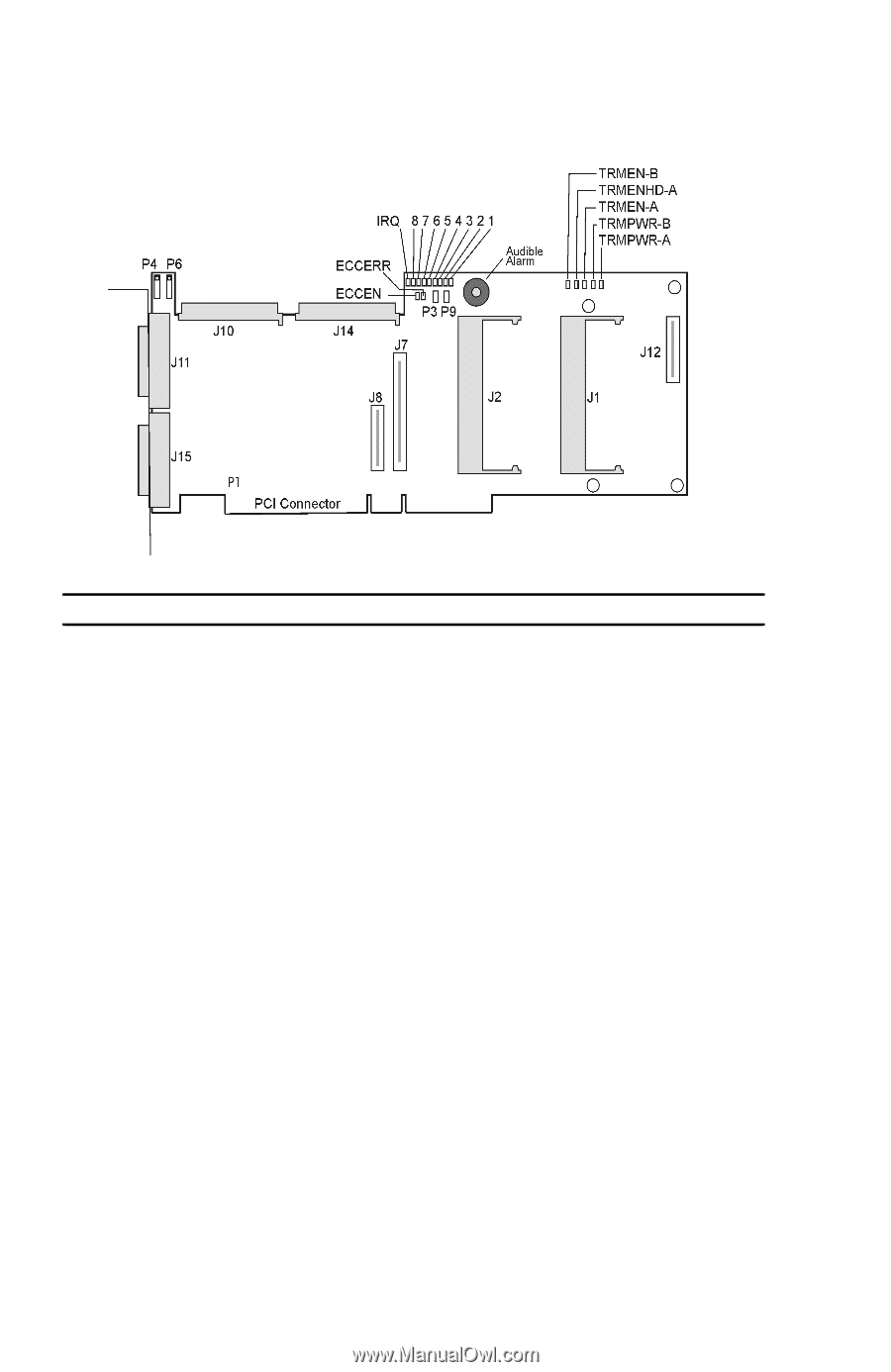
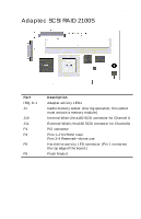
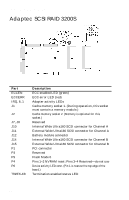
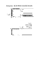
Adaptec RAID Installation Guide Adaptec SCSI RAID 3200S Part ECCEN ECCERR IRQ, 8..1 J1 J2 J7, J8 J10 J11 J12 J14 J15 P1 P3 P9 P4 P6 TRMEN-A/B Description ECC enabled LED (green) ECC error LED (red) Adapter activity LEDs Cache memory socket 1. (During operation, this socket must contain a memory module.) Cache memory socket 2. (Memory is optional for this socket.) Reserved Internal Wide Ultra160 SCSI connector for Channel A External Wide Ultra160 SCSI connector for Channel A Battery module connector Internal Wide Ultra160 SCSI connector for Channel B External Wide Ultra160 SCSI connector for Channel B PCI connector Reserved Flash Mode 0 Pins 1-2 NVRAM reset; Pins 3-4 Reserved-do not use Device activity LED conn. (Pin 1 is nearest the top edge of the board.) Termination enabled status LED A-4
-
 1
1 -
2
-
3
-
4
-
5
-
6
-
7
-
8
-
9
-
10
-
11
-
12
-
13
-
14
-
15
-
16
-
17
-
18
-
19
-
20
-
21
-
22
-
23
-
24
-
25
-
26
-
27
-
28
-
29
-
30
-
31
-
32
-
33
-
34
-
35
-
36
-
37
-
38
-
39
-
40
-
41
-
42
-
43
-
44
-
45
-
46
-
47
-
48
-
49
-
50
-
51
-
52
-
53
-
54
-
55
-
56
-
57
-
58
-
59
-
60
-
61
-
62
-
63
-
64
-
65
-
66
-
67
-
68
-
69
-
70
-
71
-
72
-
73
-
74
-
75
-
76
-
77
-
78
-
79
-
80
-
81
-
82
-
 83
83 -
 84
84 -
 85
85 -
 86
86 -
 87
87 -
 88
88 -
 89
89 -
 90
90 -
 91
91 -
 92
92 -
 93
93 -
94
-
95
-
96
-
97
-
98
-
99
-
100
-
101
-
102
-
103
-
104
-
105
-
106
-
107
-
108
-
109
-
110
-
111
 |
 |