HP Workstation x1000 hp workstations general - adaptec RAID installation guide - Page 96
LED during power-up, LEDs during controller idle, LEDs during controller active
 |
View all HP Workstation x1000 manuals
Add to My Manuals
Save this manual to your list of manuals |
Page 96 highlights
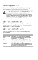
Adaptec RAID Installation Guide LED during power-up During its power-up sequence, the controller passes through the following states in sequence, as indicated by the LEDs: Note: The address translation unit (ATU), PCI bridge, and cache module (if installed) must be configured and enabled before controller initialization can be completed. If any of these components are not configured or become disabled during the Fast Idle phase, the pattern reverts to the wait pattern of the affected component. LEDs during controller idle When no commands are in progress and all bus activity has ceased, the controller enters the idle state. This is indicated by a rotating pattern in LEDs 1 through 8. LEDs during controller active When the controller is active, the LEDs indicate any of the following states: Condition Memory Mapped I/O Bridge Fast Idle LED Display LEDs 6 and 7 and LEDs 5 and 8 flash alternately while the controller waits for the host computer to initialize the ATU on the PCI bus. LEDs 5 and 7 and LEDs 6 and 8 flash alternately while the controller waits for the host computer to initialize its PCI-to-PCI bridge. After the ATU and PCI bridge have been enabled, the controller enters a fast idle pattern while waiting for the controller initialization commands. B-2
-
 1
1 -
2
-
3
-
4
-
5
-
6
-
7
-
8
-
9
-
10
-
11
-
12
-
13
-
14
-
15
-
16
-
17
-
18
-
19
-
20
-
21
-
22
-
23
-
24
-
25
-
26
-
27
-
28
-
29
-
30
-
31
-
32
-
33
-
34
-
35
-
36
-
37
-
38
-
39
-
40
-
41
-
42
-
43
-
44
-
45
-
46
-
47
-
48
-
49
-
50
-
51
-
52
-
53
-
54
-
55
-
56
-
57
-
58
-
59
-
60
-
61
-
62
-
63
-
64
-
65
-
66
-
67
-
68
-
69
-
70
-
71
-
72
-
73
-
74
-
75
-
76
-
77
-
78
-
79
-
80
-
81
-
82
-
83
-
84
-
85
-
86
-
87
-
88
-
89
-
90
-
 91
91 -
 92
92 -
 93
93 -
 94
94 -
 95
95 -
 96
96 -
 97
97 -
 98
98 -
 99
99 -
 100
100 -
 101
101 -
102
-
103
-
104
-
105
-
106
-
107
-
108
-
109
-
110
-
111
 |
 |