HP Workstation x1000 hp workstations general - adaptec RAID installation guide - Page 97
Adaptec 2400A/3200S, 3400S only
 |
View all HP Workstation x1000 manuals
Add to My Manuals
Save this manual to your list of manuals |
Page 97 highlights
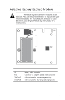
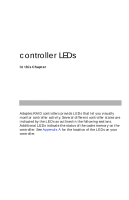
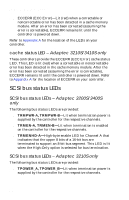
controller LEDs When the power-up sequence is complete, viewing the LEDs can help you determine the operating status of the controller. These LED patterns are also useful for troubleshooting. Refer to Appendix C for more information on interpreting LED patterns. LED Function 1 Indicates that controller is working and interrupts are enabled. During controller activity, this LED flashes four times per second. 2 Indicates the occurrence of a nonmaskable interrupt (NMI) to the I/O processor on the controller. 3 Indicates the controller's internal operating system is in its idle loop. 4 Indicates that the controller's internal operating system is processing an interrupt. 5 Reserved for future use. 6 Indicates that the cache controller is using Direct Memory Access (DMA) to perform a data transfer. 7 Indicates the controller is generating parity information for a RAID 5 array (hardware XOR). 8 Indicates that there is a command on the peripheral bus. IRQ Indicates the controller activated an interrupt on the host PCI bus. cache status LEDs Cache failure information is recorded in the controller error log and can be viewed using the Event Log window in Storage Manager. cache status LEDs - Adaptec 2400A/3200S/ 3400S only The following LEDs on the Adaptec RAID controller indicate the status of the onboard cache RAM: s ECCEN (ECC Enable)-Lit (green) when the installed cache module has ECC. B-3
-
 1
1 -
2
-
3
-
4
-
5
-
6
-
7
-
8
-
9
-
10
-
11
-
12
-
13
-
14
-
15
-
16
-
17
-
18
-
19
-
20
-
21
-
22
-
23
-
24
-
25
-
26
-
27
-
28
-
29
-
30
-
31
-
32
-
33
-
34
-
35
-
36
-
37
-
38
-
39
-
40
-
41
-
42
-
43
-
44
-
45
-
46
-
47
-
48
-
49
-
50
-
51
-
52
-
53
-
54
-
55
-
56
-
57
-
58
-
59
-
60
-
61
-
62
-
63
-
64
-
65
-
66
-
67
-
68
-
69
-
70
-
71
-
72
-
73
-
74
-
75
-
76
-
77
-
78
-
79
-
80
-
81
-
82
-
83
-
84
-
85
-
86
-
87
-
88
-
89
-
90
-
91
-
 92
92 -
 93
93 -
 94
94 -
 95
95 -
 96
96 -
 97
97 -
 98
98 -
 99
99 -
 100
100 -
 101
101 -
 102
102 -
103
-
104
-
105
-
106
-
107
-
108
-
109
-
110
-
111
 |
 |