IBM 8669 Hardware Maintenance Manual - Page 21
Diagnostics, Diagnostic tools overview, Identifying problems using LEDs, Power supply LEDs
 |
UPC - 087944636496
View all IBM 8669 manuals
Add to My Manuals
Save this manual to your list of manuals |
Page 21 highlights
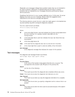
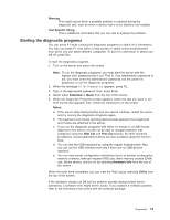
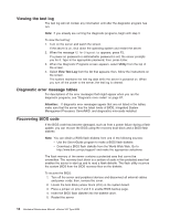
Diagnostics This section provides basic troubleshooting information to help you resolve some common problems that might occur with the server. Diagnostic tools overview The following tools are available to help you identify and resolve hardware-related problems: v POST beep codes, error messages, and error logs The power-on self-test (POST) generates beep codes and messages to indicate successful test completion or the detection of a problem. See "POST" on page 12 for more information. v Diagnostic programs and error messages The server diagnostic programs are stored in upgradable read-only memory (ROM) on the system board. These programs are the primary method of testing the major components of the server. See "Diagnostic programs and error messages" on page 13 for more information. v Light path diagnostics The server has light-emitting diodes (LEDs) to help you identify problems with server components. These LEDs are part of the light-path diagnostics that are built into the server. By following the path of lights, you can quickly identify the type of system error that occurred. See "Light path diagnostics" for more information. Identifying problems using LEDs The server has LEDs to help you identify problems with some server components. These LEDs are part of the light path diagnostics built into the server. By following the path of lights, you can identify the type of system error that occurred. See the following sections for more information. Power supply LEDs The AC and DC Power LEDs on the power supply provide status information about the power supply. See "Power supply LED errors" on page 92. Light path diagnostics You can use the light path diagnostics built into the server to quickly identify the type of system error that occurred. The diagnostics panel is under the air baffle. The server is designed so that any LEDs that are illuminated remain illuminated when the server shuts down as long as the AC power source is good and the power supplies can supply +5V DC current to the server. This feature helps you isolate the problem if an error causes the server to shut down. See "Light path diagnostics" on page 12. Diagnostics panel The following illustration shows the LEDs on the diagnostics panel on the system board. See "Light path diagnostics" on page 12 for information on identifying © Copyright IBM Corp. 2000, 2001 11
-
 1
1 -
2
-
3
-
4
-
5
-
6
-
7
-
8
-
9
-
10
-
11
-
12
-
13
-
14
-
15
-
 16
16 -
 17
17 -
 18
18 -
 19
19 -
 20
20 -
 21
21 -
 22
22 -
 23
23 -
 24
24 -
 25
25 -
 26
26 -
27
-
28
-
29
-
30
-
31
-
32
-
33
-
34
-
35
-
36
-
37
-
38
-
39
-
40
-
41
-
42
-
43
-
44
-
45
-
46
-
47
-
48
-
49
-
50
-
51
-
52
-
53
-
54
-
55
-
56
-
57
-
58
-
59
-
60
-
61
-
62
-
63
-
64
-
65
-
66
-
67
-
68
-
69
-
70
-
71
-
72
-
73
-
74
-
75
-
76
-
77
-
78
-
79
-
80
-
81
-
82
-
83
-
84
-
85
-
86
-
87
-
88
-
89
-
90
-
91
-
92
-
93
-
94
-
95
-
96
-
97
-
98
-
99
-
100
-
101
-
102
-
103
-
104
-
105
-
106
-
107
-
108
-
109
-
110
-
111
-
112
-
113
-
114
-
115
-
116
-
117
-
118
-
119
-
120
-
121
-
122
-
123
-
124
-
125
-
126
-
127
-
128
-
129
-
130
-
131
-
132
-
133
-
134
-
135
-
136
-
137
-
138
-
139
-
140
-
141
-
142
-
143
-
144
-
145
-
146
-
147
-
148
-
149
-
150
-
151
-
152
-
153
-
154
-
155
-
156
 |
 |
