IBM 8669 Hardware Maintenance Manual - Page 44
System board layout, System board options connectors
 |
UPC - 087944636496
View all IBM 8669 manuals
Add to My Manuals
Save this manual to your list of manuals |
Page 44 highlights
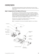
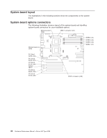
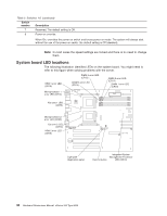
System board layout The illustrations in the following sections show the components on the system board. System board options connectors The following illustration shows a layout of the system board and identifies system-board connectors for user-installable options. Microprocessor 1 (U68) VRM 1 connector (J37) Microprocessor 2 (U69) DIMM 4 (J4) DIMM 3 (J3) DIMM 2 (J2) DIMM 1 (J1) PCI Slot 1 32-bit (J44) PCI Slot 2 64-bit (J41) PCI Slot 3 64-bit (J42) Battery (BH1) PCI Slot 4 64-bit (J29) PCI Slot 5 64-bit (J30) VRM 2 connector (J38) 34 Hardware Maintenance Manual: xSeries 342 Type 8669
-
 1
1 -
2
-
3
-
4
-
5
-
6
-
7
-
8
-
9
-
10
-
11
-
12
-
13
-
14
-
15
-
16
-
17
-
18
-
19
-
20
-
21
-
22
-
23
-
24
-
25
-
26
-
27
-
28
-
29
-
30
-
31
-
32
-
33
-
34
-
35
-
36
-
37
-
38
-
 39
39 -
 40
40 -
 41
41 -
 42
42 -
 43
43 -
 44
44 -
 45
45 -
 46
46 -
 47
47 -
 48
48 -
 49
49 -
50
-
51
-
52
-
53
-
54
-
55
-
56
-
57
-
58
-
59
-
60
-
61
-
62
-
63
-
64
-
65
-
66
-
67
-
68
-
69
-
70
-
71
-
72
-
73
-
74
-
75
-
76
-
77
-
78
-
79
-
80
-
81
-
82
-
83
-
84
-
85
-
86
-
87
-
88
-
89
-
90
-
91
-
92
-
93
-
94
-
95
-
96
-
97
-
98
-
99
-
100
-
101
-
102
-
103
-
104
-
105
-
106
-
107
-
108
-
109
-
110
-
111
-
112
-
113
-
114
-
115
-
116
-
117
-
118
-
119
-
120
-
121
-
122
-
123
-
124
-
125
-
126
-
127
-
128
-
129
-
130
-
131
-
132
-
133
-
134
-
135
-
136
-
137
-
138
-
139
-
140
-
141
-
142
-
143
-
144
-
145
-
146
-
147
-
148
-
149
-
150
-
151
-
152
-
153
-
154
-
155
-
156
 |
 |

System board layout
The illustrations in the following sections show the components on the system
board.
System board options connectors
The following illustration shows a layout of the system board and identifies
system-board connectors for user-installable options.
DIMM 4 (J4)
DIMM 3 (J3)
DIMM 2 (J2)
DIMM 1 (J1)
PCI Slot 1
32-bit (J44)
PCI Slot 2
64-bit (J41)
PCI Slot 3
64-bit (J42)
PCI Slot 4
64-bit (J29)
PCI Slot 5
64-bit (J30)
Battery
(BH1)
Microprocessor 1
(U68)
Microprocessor 2
(U69)
VRM 1 connector (J37)
VRM 2 connector (J38)
34
Hardware Maintenance Manual: xSeries 342 Type 8669