IBM 8669 Hardware Maintenance Manual - Page 84
Ethernet port connector, Integrated System Management Processor ports
 |
UPC - 087944636496
View all IBM 8669 manuals
Add to My Manuals
Save this manual to your list of manuals |
Page 84 highlights
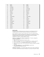
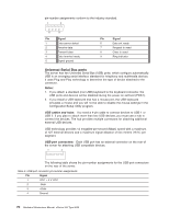
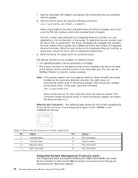
1. Add the redundant NIC adapter according to the instructions that are provided with the adapter. 2. Load the device driver by using the following command: LOAD d:\path\PCNTNW.LAN PRIMARY=x SECONDARY=y where d and path are the drive and path where the driver is located, and x and y are the PCI slot numbers where the redundant pair is located. The slot number associated with the integrated Ethernet controller can vary depending on the configuration of the server. To determine the slot number, load the driver with no parameters. The driver will display the available slot numbers. The slot number that is greater than 10000 will be the slot number of integrated Ethernet controller. When the slot number of the integrated Ethernet controller is determined, reload the driver with the appropriate parameters. 3. When the driver is loaded, bind it to a protocol stack. The failover function is now enabled. If a failover occurs: v The operating system console generates a message. v The custom counters for the device driver contain variables that define the state of the failover function and the location of the redundant pair. You can use the NetWare Monitor to view the custom counters. Note: If the primary adapter was hot-replaced while the Ethernet traffic was being handled by the secondary Ethernet controller, the traffic does not automatically switch back to the primary adapter when the primary adapter comes back online. In this case, issue the command: LOAD d:\path\PCNTNW SCAN where d and path are the drive and path where the driver is located. This command causes the device driver to locate the primary adapter and switch the Ethernet traffic to it. Ethernet port connector: The following table shows the pin-number assignments for the RJ-45 connector. These assignments apply to both 10BASE-T and 100BASE-TX devices. Table 4. Ethernet RJ-45 connector pin-number assignments. Pin Signal Pin 1 Transmit data+ 5 2 Transmit data- 6 3 Receive data+ 7 4 Not connected 8 Signal Not connected Receive data Not connected Not connected Integrated System Management Processor ports The integrated system management (ISM) ports (ISM-A and ISM-B) use a dual RJ-45 connector to interconnect ISM processors of several servers through an optional Remote Supervisor Adapter. 74 Hardware Maintenance Manual: xSeries 342 Type 8669
-
 1
1 -
2
-
3
-
4
-
5
-
6
-
7
-
8
-
9
-
10
-
11
-
12
-
13
-
14
-
15
-
16
-
17
-
18
-
19
-
20
-
21
-
22
-
23
-
24
-
25
-
26
-
27
-
28
-
29
-
30
-
31
-
32
-
33
-
34
-
35
-
36
-
37
-
38
-
39
-
40
-
41
-
42
-
43
-
44
-
45
-
46
-
47
-
48
-
49
-
50
-
51
-
52
-
53
-
54
-
55
-
56
-
57
-
58
-
59
-
60
-
61
-
62
-
63
-
64
-
65
-
66
-
67
-
68
-
69
-
70
-
71
-
72
-
73
-
74
-
75
-
76
-
77
-
78
-
 79
79 -
 80
80 -
 81
81 -
 82
82 -
 83
83 -
 84
84 -
 85
85 -
 86
86 -
 87
87 -
 88
88 -
 89
89 -
90
-
91
-
92
-
93
-
94
-
95
-
96
-
97
-
98
-
99
-
100
-
101
-
102
-
103
-
104
-
105
-
106
-
107
-
108
-
109
-
110
-
111
-
112
-
113
-
114
-
115
-
116
-
117
-
118
-
119
-
120
-
121
-
122
-
123
-
124
-
125
-
126
-
127
-
128
-
129
-
130
-
131
-
132
-
133
-
134
-
135
-
136
-
137
-
138
-
139
-
140
-
141
-
142
-
143
-
144
-
145
-
146
-
147
-
148
-
149
-
150
-
151
-
152
-
153
-
154
-
155
-
156
 |
 |
