IBM 8669 Hardware Maintenance Manual - Page 47
System board jumper blocks, Boot block jumper, Switch, number, Description
 |
UPC - 087944636496
View all IBM 8669 manuals
Add to My Manuals
Save this manual to your list of manuals |
Page 47 highlights
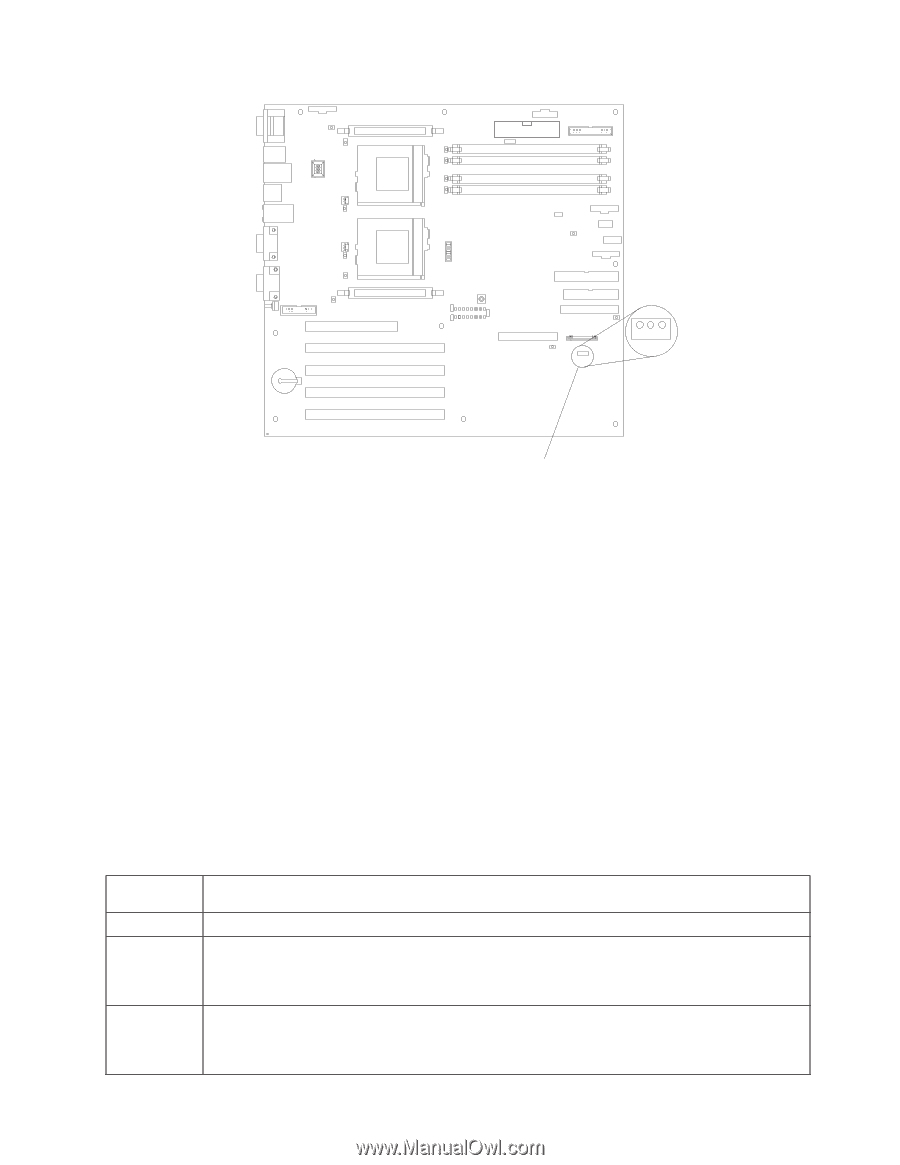
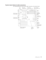
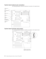
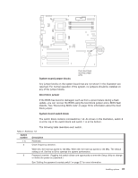
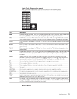
123 System board jumper blocks Flash boot block recovery jumper (J16) Any jumper blocks on the system board that are not shown in the illustration are reserved. For normal operation of the system, no jumpers should be installed on any of the jumper blocks. Boot block jumper If the BIOS has become damaged, such as from a power failure during a flash update, you can recover the BIOS using the boot block jumper and a BIOS flash diskette. See "Recovering BIOS code" on page 16 for information about the boot block jumper. System board switch block The switch block contains microswitches 1-8. As shown in this illustration, switch 8 is at the top of the switch block and switch 1 is at the bottom. The following table describes each switch. Table 2. Switches 1-8 Switch number Description 1- 4 Reserved 5 Clock frequency selection. When On, the host bus speed is 100 Mhz. When Off, the host bus speed is 133 Mhz. The default setting is off. Set this to Off to optimize the system performance. 6 Password override. (Toggling this switch allows one opportunity to enter the Setup Utility to change or delete the power-on password.) See "Setting the password override switch" on page 27 for more information. Installing options 37
-
 1
1 -
2
-
3
-
4
-
5
-
6
-
7
-
8
-
9
-
10
-
11
-
12
-
13
-
14
-
15
-
16
-
17
-
18
-
19
-
20
-
21
-
22
-
23
-
24
-
25
-
26
-
27
-
28
-
29
-
30
-
31
-
32
-
33
-
34
-
35
-
36
-
37
-
38
-
39
-
40
-
41
-
 42
42 -
 43
43 -
 44
44 -
 45
45 -
 46
46 -
 47
47 -
 48
48 -
 49
49 -
 50
50 -
 51
51 -
 52
52 -
53
-
54
-
55
-
56
-
57
-
58
-
59
-
60
-
61
-
62
-
63
-
64
-
65
-
66
-
67
-
68
-
69
-
70
-
71
-
72
-
73
-
74
-
75
-
76
-
77
-
78
-
79
-
80
-
81
-
82
-
83
-
84
-
85
-
86
-
87
-
88
-
89
-
90
-
91
-
92
-
93
-
94
-
95
-
96
-
97
-
98
-
99
-
100
-
101
-
102
-
103
-
104
-
105
-
106
-
107
-
108
-
109
-
110
-
111
-
112
-
113
-
114
-
115
-
116
-
117
-
118
-
119
-
120
-
121
-
122
-
123
-
124
-
125
-
126
-
127
-
128
-
129
-
130
-
131
-
132
-
133
-
134
-
135
-
136
-
137
-
138
-
139
-
140
-
141
-
142
-
143
-
144
-
145
-
146
-
147
-
148
-
149
-
150
-
151
-
152
-
153
-
154
-
155
-
156
 |
 |