IBM 8669 Hardware Maintenance Manual - Page 69
heat sink onto the tab located on the front of the microprocessor socket
 |
UPC - 087944636496
View all IBM 8669 manuals
Add to My Manuals
Save this manual to your list of manuals |
Page 69 highlights
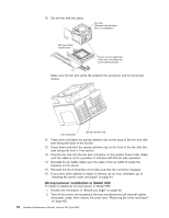
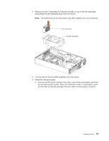
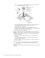
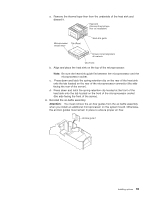
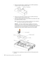
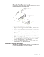
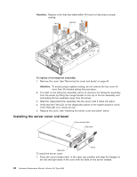
a. Remove the thermal tape liner from the underside of the heat sink and discard it. Heat sink (Remove thermal tape liner on installation) Microprocessor Tab (Rear) release lever Heat-sink guide Ensure correct alignment of heat sink Tab (Front) b. Align and place the heat sink on the top of the microprocessor. Note: Be sure the heat-sink guide fits between the microprocessor and the microprocessor socket. c. Press down and latch the spring-retention clip on the rear of the heat sink onto the tab located on the rear of the microprocessor connector (the side facing the rear of the server). d. Press down and latch the spring-retention clip located at the front of the heat sink onto the tab located on the front of the microprocessor socket (the side facing the front of the server). 8. Reinstall the air-baffle assembly. Attention: You must remove the air-flow guides from the air-baffle assembly when you install an additional microprocessor on the system board. Otherwise, the air-flow guides must remain in place to ensure proper air flow. Air-flow guide 1 Installing options 59
-
 1
1 -
2
-
3
-
4
-
5
-
6
-
7
-
8
-
9
-
10
-
11
-
12
-
13
-
14
-
15
-
16
-
17
-
18
-
19
-
20
-
21
-
22
-
23
-
24
-
25
-
26
-
27
-
28
-
29
-
30
-
31
-
32
-
33
-
34
-
35
-
36
-
37
-
38
-
39
-
40
-
41
-
42
-
43
-
44
-
45
-
46
-
47
-
48
-
49
-
50
-
51
-
52
-
53
-
54
-
55
-
56
-
57
-
58
-
59
-
60
-
61
-
62
-
63
-
 64
64 -
 65
65 -
 66
66 -
 67
67 -
 68
68 -
 69
69 -
 70
70 -
 71
71 -
 72
72 -
 73
73 -
 74
74 -
75
-
76
-
77
-
78
-
79
-
80
-
81
-
82
-
83
-
84
-
85
-
86
-
87
-
88
-
89
-
90
-
91
-
92
-
93
-
94
-
95
-
96
-
97
-
98
-
99
-
100
-
101
-
102
-
103
-
104
-
105
-
106
-
107
-
108
-
109
-
110
-
111
-
112
-
113
-
114
-
115
-
116
-
117
-
118
-
119
-
120
-
121
-
122
-
123
-
124
-
125
-
126
-
127
-
128
-
129
-
130
-
131
-
132
-
133
-
134
-
135
-
136
-
137
-
138
-
139
-
140
-
141
-
142
-
143
-
144
-
145
-
146
-
147
-
148
-
149
-
150
-
151
-
152
-
153
-
154
-
155
-
156
 |
 |
