IBM 8669 Hardware Maintenance Manual - Page 61
Memory modules, Notes, Save Settings.
 |
UPC - 087944636496
View all IBM 8669 manuals
Add to My Manuals
Save this manual to your list of manuals |
Page 61 highlights
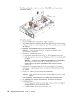
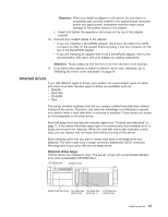
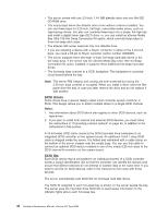
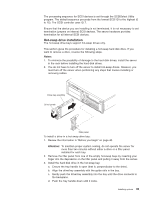
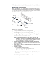
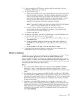
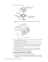
8. If you are installing a SCSI device, continue with the next step. If you are installing an IDE device, go to step 11. 9. To install a SCSI device: a. Attach the connector on the 1-drop SCSI cable for the non-hot-swap drive bays to the back of the drive. The cable is shipped restrained in a cable clamp on the bottom of the server chassis near the bays. Connect the other end of the cable to SCSI channel A on the system board, if it is not already attached. See "System board internal cable connectors" on page 35 for the location of the SCSI channel A connector. Note: If you want to install more than one optional SCSI 5.25-inch device, install an optional SCSI adapter to control the device. b. Connect a power cable to the back of the drive. Power cables for non-hot-swap drives come installed in the server. The connectors are keyed and can be inserted only one way. c. Continue with step 11 10. To install an IDE device, such as a CD-ROM drive or a DVD-ROM drive, use the two-drop IDE cable that comes with the option: a. Remove the cable connecting the CD-ROM drive to the IDE connector on the system board. b. Using the two-drop cable that came with your IDE option, connect the CD-ROM drive and the IDE device to the IDE connector on the system board. c. Set the jumper on the back of the new IDE device to slave. 11. If you have other options to install or remove, do so now; otherwise, go to "Installing the server cover and bezel" on page 64. Memory modules Adding memory to the server is an easy way to make programs run faster. You can increase the amount of memory in the server by installing options called memory-module kits. Each kit contains one industry-standard, dual inline memory module (DIMM). The server uses a two-way interleaved memory configuration. You must install matched pairs of memory kits, but the set in slots 1 and 4 do not need to be the same size as the set in slots 2 and 3. Notes: 1. The server comes with two dual inline memory modules (DIMMs) installed in DIMM slots 1 and 4. Install additional DIMMs as a matched pair in DIMM connectors 2 and 3 and as instructed in the documentation that comes with your option. 2. Your xSeries 342 server supports 128 MB, 256 MB, 512 MB, and 1 GB DIMMs. You must install the DIMMs in pairs of the same size. Place pair 1 in slots 1 and 4 and pair 2 in slots 2 and 3. Refer to the ServerProven™ list on the World Wide Web at http://www.ibm.com/pc/compat for information about memory modules for use with the server. 3. Installing or removing DIMMs changes the configuration information in the server. Therefore, after installing or removing a DIMM, you must save the new configuration information in the Configuration/Setup Utility program. When you restart the server, the system displays a message indicating that the memory configuration has changed. Start the Configuration/Setup Utility program and select Save Settings. Installing options 51
-
 1
1 -
2
-
3
-
4
-
5
-
6
-
7
-
8
-
9
-
10
-
11
-
12
-
13
-
14
-
15
-
16
-
17
-
18
-
19
-
20
-
21
-
22
-
23
-
24
-
25
-
26
-
27
-
28
-
29
-
30
-
31
-
32
-
33
-
34
-
35
-
36
-
37
-
38
-
39
-
40
-
41
-
42
-
43
-
44
-
45
-
46
-
47
-
48
-
49
-
50
-
51
-
52
-
53
-
54
-
55
-
 56
56 -
 57
57 -
 58
58 -
 59
59 -
 60
60 -
 61
61 -
 62
62 -
 63
63 -
 64
64 -
 65
65 -
 66
66 -
67
-
68
-
69
-
70
-
71
-
72
-
73
-
74
-
75
-
76
-
77
-
78
-
79
-
80
-
81
-
82
-
83
-
84
-
85
-
86
-
87
-
88
-
89
-
90
-
91
-
92
-
93
-
94
-
95
-
96
-
97
-
98
-
99
-
100
-
101
-
102
-
103
-
104
-
105
-
106
-
107
-
108
-
109
-
110
-
111
-
112
-
113
-
114
-
115
-
116
-
117
-
118
-
119
-
120
-
121
-
122
-
123
-
124
-
125
-
126
-
127
-
128
-
129
-
130
-
131
-
132
-
133
-
134
-
135
-
136
-
137
-
138
-
139
-
140
-
141
-
142
-
143
-
144
-
145
-
146
-
147
-
148
-
149
-
150
-
151
-
152
-
153
-
154
-
155
-
156
 |
 |
