IBM 8669 Hardware Maintenance Manual - Page 75
Connecting external options, Cabling requirements, Setting SCSI IDs for external devices
 |
UPC - 087944636496
View all IBM 8669 manuals
Add to My Manuals
Save this manual to your list of manuals |
Page 75 highlights
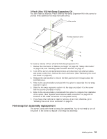
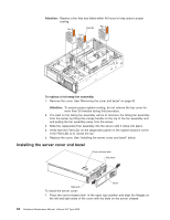
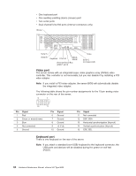
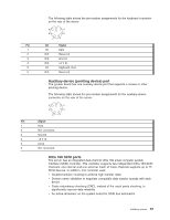
2. Close the cover-release latch. To install the bezel: 1. Align the trim bezel with the front of the server. 2. Press inward on the top sides of the bezel and press the bezel toward the server until it clicks into place. To complete the installation: If you disconnected any cables from the back of the server, reconnect the cables; then, plug the power cords into properly grounded electrical outlets. Connecting external options If you install a SCSI adapter, you can attach a SCSI storage expansion enclosure to the server. Cabling requirements To select and order the correct cables for use with external devices, contact your IBM reseller or IBM marketing representative. For information about the maximum length of SCSI cable between the terminated ends of the cable, see ANSI SCSI Standards: v X3.131-1986 (SCSI) v X3.131-1994 (SCSI-2) v X3T10/1071D Adhering to these standards ensures that the server operates properly. Setting SCSI IDs for external devices Each SCSI device that is connected to a SCSI controller must have a unique SCSI ID, so that the SCSI controller can identify the devices and ensure that different devices do not attempt to transfer data at the same time. SCSI devices that are connected to different SCSI controllers can have duplicate SCSI IDs. The SCSI controller uses one of the SCSI IDs; the default SCSI ID for the SCSI controller is 7. Refer to the instructions that come with the SCSI devices for more information about setting a SCSI ID. Installation procedure To attach an external device: 1. Turn off the server and all attached devices. 2. Follow the instructions that come with the option to prepare it for installation and to connect it to the server. Input/Output ports This section provides information about the input/output (I/O) ports on the rear of the server. These ports include the following: v One video port v Two integrated system management (RS-485) ports v One management port (not supported) v Two Universal Serial Bus (USB) ports v One Ethernet port Installing options 65
-
 1
1 -
2
-
3
-
4
-
5
-
6
-
7
-
8
-
9
-
10
-
11
-
12
-
13
-
14
-
15
-
16
-
17
-
18
-
19
-
20
-
21
-
22
-
23
-
24
-
25
-
26
-
27
-
28
-
29
-
30
-
31
-
32
-
33
-
34
-
35
-
36
-
37
-
38
-
39
-
40
-
41
-
42
-
43
-
44
-
45
-
46
-
47
-
48
-
49
-
50
-
51
-
52
-
53
-
54
-
55
-
56
-
57
-
58
-
59
-
60
-
61
-
62
-
63
-
64
-
65
-
66
-
67
-
68
-
69
-
 70
70 -
 71
71 -
 72
72 -
 73
73 -
 74
74 -
 75
75 -
 76
76 -
 77
77 -
 78
78 -
 79
79 -
 80
80 -
81
-
82
-
83
-
84
-
85
-
86
-
87
-
88
-
89
-
90
-
91
-
92
-
93
-
94
-
95
-
96
-
97
-
98
-
99
-
100
-
101
-
102
-
103
-
104
-
105
-
106
-
107
-
108
-
109
-
110
-
111
-
112
-
113
-
114
-
115
-
116
-
117
-
118
-
119
-
120
-
121
-
122
-
123
-
124
-
125
-
126
-
127
-
128
-
129
-
130
-
131
-
132
-
133
-
134
-
135
-
136
-
137
-
138
-
139
-
140
-
141
-
142
-
143
-
144
-
145
-
146
-
147
-
148
-
149
-
150
-
151
-
152
-
153
-
154
-
155
-
156
 |
 |
