IBM 8669 Hardware Maintenance Manual - Page 80
Universal Serial Bus ports, USB cables and hubs, USB-port connectors
 |
UPC - 087944636496
View all IBM 8669 manuals
Add to My Manuals
Save this manual to your list of manuals |
Page 80 highlights
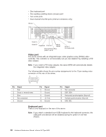
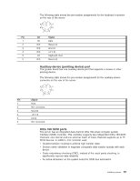
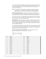
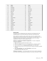
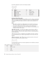
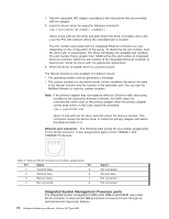
pin-number assignments conform to the industry standard. 1 5 6 9 Pin Signal 1 Data carrier detect 2 Receive data 3 Transmit data 4 Data terminal ready 5 Signal ground Pin Signal 6 Data set ready 7 Request to send 8 Clear to send 9 Ring indicator Universal Serial Bus ports The server has two Universal Serial Bus (USB) ports, which configure automatically. USB is an emerging serial interface standard for telephony and multimedia devices. It uses Plug and Play technology to determine the type of device attached to the connector. Notes: 1. If you attach a standard (non-USB) keyboard to the keyboard connector, the USB ports and devices will be disabled during the power-on self-test (POST). 2. If you install a USB keyboard that has a mouse port, the USB keyboard emulates a mouse and you will not be able to disable the mouse settings in the Configuration/Setup Utility program. USB cables and hubs: You need a 4-pin cable to connect devices to USB 1 or USB 2. If you plan to attach more than two USB devices, you must use a hub to connect the devices. The hub provides multiple connectors for attaching additional external USB devices. USB technology provides 12 megabits-per-second (Mbps) speed with a maximum of 127 external devices and a maximum signal distance of five meters (16 ft.) per segment. USB-port connectors: Each USB port has an external connector on the rear of the server for attaching USB compatible devices. 1 4 The following table shows the pin-number assignments for the USB-port connectors on the rear of the server. Table 3. USB-port connector pin-number assignments Pin Signal 1 VCC + 5 V VCC 2 -Data 3 +Data 4 Ground 70 Hardware Maintenance Manual: xSeries 342 Type 8669
-
 1
1 -
2
-
3
-
4
-
5
-
6
-
7
-
8
-
9
-
10
-
11
-
12
-
13
-
14
-
15
-
16
-
17
-
18
-
19
-
20
-
21
-
22
-
23
-
24
-
25
-
26
-
27
-
28
-
29
-
30
-
31
-
32
-
33
-
34
-
35
-
36
-
37
-
38
-
39
-
40
-
41
-
42
-
43
-
44
-
45
-
46
-
47
-
48
-
49
-
50
-
51
-
52
-
53
-
54
-
55
-
56
-
57
-
58
-
59
-
60
-
61
-
62
-
63
-
64
-
65
-
66
-
67
-
68
-
69
-
70
-
71
-
72
-
73
-
74
-
 75
75 -
 76
76 -
 77
77 -
 78
78 -
 79
79 -
 80
80 -
 81
81 -
 82
82 -
 83
83 -
 84
84 -
 85
85 -
86
-
87
-
88
-
89
-
90
-
91
-
92
-
93
-
94
-
95
-
96
-
97
-
98
-
99
-
100
-
101
-
102
-
103
-
104
-
105
-
106
-
107
-
108
-
109
-
110
-
111
-
112
-
113
-
114
-
115
-
116
-
117
-
118
-
119
-
120
-
121
-
122
-
123
-
124
-
125
-
126
-
127
-
128
-
129
-
130
-
131
-
132
-
133
-
134
-
135
-
136
-
137
-
138
-
139
-
140
-
141
-
142
-
143
-
144
-
145
-
146
-
147
-
148
-
149
-
150
-
151
-
152
-
153
-
154
-
155
-
156
 |
 |
