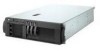
IBM 8669 Hardware Maintenance Manual - Page 79
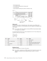
Serial ports, Viewing or changing the serial-port assignments, Serial-port connectors
 |
UPC - 087944636496
View all IBM 8669 manuals
Add to My Manuals
Save this manual to your list of manuals |
Page 79 highlights
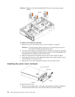
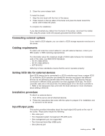
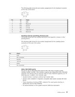
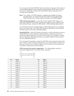
Pin Signal 15 Ground 16 DIFFSENS 17 Term power 18 Term power 19 Reserved 20 Ground 21 +Attention 22 Ground 23 +Busy 24 +Acknowledge 25 +Reset 26 +Message 27 +Select 28 +Control/Data 29 +Request 30 +Input/Output 31 +Data 8 32 +Data 9 33 +Data 10 34 +Data 11 Pin Signal 49 Ground 50 Ground 51 Term power 52 Term power 53 Reserved 54 Ground 55 -Attention 56 Ground 57 -Busy 58 -Acknowledge 59 -Reset 60 -Message 61 -Select 62 -Control/Data 63 -Request 64 -Input/Output 65 -Data 8 66 -Data9 67 -Data 10 68 -Data 11 Serial ports The server has two standard serial ports, Serial port A and Serial port B. The operating system can use both serial ports, Serial port A and Serial port B. Some application programs require specific ports, and some modems function properly only at certain communication port addresses. You might need to use the Configuration/Setup Utility program to change communication port address assignments to prevent or resolve address conflicts. Viewing or changing the serial-port assignments: To view or change the serial-port assignments: 1. Restart the server and watch the monitor screen. 2. When the message Press F1 for Configuration/Setup appears, press F1. 3. From the main menu, click Devices and I/O Ports; then, press Enter. 4. Select the serial port; then, use the arrow keys to advance through the settings available. 5. Select Save Settings; then, select Exit Setup to exit from the Configuration/Setup Utility main menu. Serial-port connectors: The following table shows the pin-number assignments for the 9-pin, male D-shell serial-port connectors on the rear of the server. These Installing options 69
-
 1
1 -
2
-
3
-
4
-
5
-
6
-
7
-
8
-
9
-
10
-
11
-
12
-
13
-
14
-
15
-
16
-
17
-
18
-
19
-
20
-
21
-
22
-
23
-
24
-
25
-
26
-
27
-
28
-
29
-
30
-
31
-
32
-
33
-
34
-
35
-
36
-
37
-
38
-
39
-
40
-
41
-
42
-
43
-
44
-
45
-
46
-
47
-
48
-
49
-
50
-
51
-
52
-
53
-
54
-
55
-
56
-
57
-
58
-
59
-
60
-
61
-
62
-
63
-
64
-
65
-
66
-
67
-
68
-
69
-
70
-
71
-
72
-
73
-
 74
74 -
 75
75 -
 76
76 -
 77
77 -
 78
78 -
 79
79 -
 80
80 -
 81
81 -
 82
82 -
 83
83 -
 84
84 -
85
-
86
-
87
-
88
-
89
-
90
-
91
-
92
-
93
-
94
-
95
-
96
-
97
-
98
-
99
-
100
-
101
-
102
-
103
-
104
-
105
-
106
-
107
-
108
-
109
-
110
-
111
-
112
-
113
-
114
-
115
-
116
-
117
-
118
-
119
-
120
-
121
-
122
-
123
-
124
-
125
-
126
-
127
-
128
-
129
-
130
-
131
-
132
-
133
-
134
-
135
-
136
-
137
-
138
-
139
-
140
-
141
-
142
-
143
-
144
-
145
-
146
-
147
-
148
-
149
-
150
-
151
-
152
-
153
-
154
-
155
-
156
 |
 |
