IBM 8669 Hardware Maintenance Manual - Page 48
System board LED locations
 |
UPC - 087944636496
View all IBM 8669 manuals
Add to My Manuals
Save this manual to your list of manuals |
Page 48 highlights
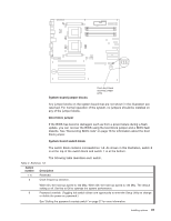
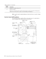
Table 2. Switches 1-8 (continued) Switch number Description 7 Reserved. The default setting is Off. 8 Power-on override. When On, overrides the power-on switch and forces power-on mode. The system will always start without the use of the power-on switch. the default setting is Off (disabled). Note: In most cases the speed settings are locked and there is no need to change them. System board LED locations The following illustration identifies LEDs on the system board. You might need to refer to this figure when solving problems with the server. VRM 1 error LED (CR19) DIMM 4 error LED (CR15) DIMM 3 error LED (CR14) DIMM 2 error LED (CR17) DIMM 1 error LED (CR16) Microprocessor 1 error LED (CR13) Fan sink 1 LED (CR78) Microprocessor 2 error LED (CR20) Fan sink 2 LED (CR79) VRM 2 error LED (CR18) Light path diagnostics panel Integrated System Management Processor Remind button LED (CR70) 38 Hardware Maintenance Manual: xSeries 342 Type 8669
-
 1
1 -
2
-
3
-
4
-
5
-
6
-
7
-
8
-
9
-
10
-
11
-
12
-
13
-
14
-
15
-
16
-
17
-
18
-
19
-
20
-
21
-
22
-
23
-
24
-
25
-
26
-
27
-
28
-
29
-
30
-
31
-
32
-
33
-
34
-
35
-
36
-
37
-
38
-
39
-
40
-
41
-
42
-
 43
43 -
 44
44 -
 45
45 -
 46
46 -
 47
47 -
 48
48 -
 49
49 -
 50
50 -
 51
51 -
 52
52 -
 53
53 -
54
-
55
-
56
-
57
-
58
-
59
-
60
-
61
-
62
-
63
-
64
-
65
-
66
-
67
-
68
-
69
-
70
-
71
-
72
-
73
-
74
-
75
-
76
-
77
-
78
-
79
-
80
-
81
-
82
-
83
-
84
-
85
-
86
-
87
-
88
-
89
-
90
-
91
-
92
-
93
-
94
-
95
-
96
-
97
-
98
-
99
-
100
-
101
-
102
-
103
-
104
-
105
-
106
-
107
-
108
-
109
-
110
-
111
-
112
-
113
-
114
-
115
-
116
-
117
-
118
-
119
-
120
-
121
-
122
-
123
-
124
-
125
-
126
-
127
-
128
-
129
-
130
-
131
-
132
-
133
-
134
-
135
-
136
-
137
-
138
-
139
-
140
-
141
-
142
-
143
-
144
-
145
-
146
-
147
-
148
-
149
-
150
-
151
-
152
-
153
-
154
-
155
-
156
 |
 |
