IBM 8669 Hardware Maintenance Manual - Page 78
SCSI cabling requirements, Setting SCSI IDs, SCSI connector pin-number assignments
 |
UPC - 087944636496
View all IBM 8669 manuals
Add to My Manuals
Save this manual to your list of manuals |
Page 78 highlights
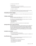
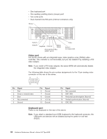
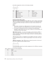
You can use the external LVD SCSI channel connector, on the rear of the server, to connect different types of small computer system interface (SCSI) devices. Inside the server, a SCSI cable connects the internal SCSI channel connector to the hot-swap drive backplane. Note: If you install a PCI RAID adapter to configure and manage the internal hot-swap drives, you must move the SCSI cable from the system-board SCSI connector to an internal channel connector on the RAID adapter. SCSI cabling requirements: If you plan to attach external SCSI devices, you must order additional SCSI cables. To select and order the correct cables for use with external devices, contact your IBM reseller or IBM marketing representative. For information about the maximum length of SCSI cable between the terminated ends of the cable, refer to the ANSI SCSI standards. Adhering to these standards will help ensure that the server operates properly. Setting SCSI IDs: Each SCSI device connected to a SCSI controller must have a unique SCSI ID. This ID enables the SCSI controller to identify the device and ensure that different devices on the same SCSI channel do not attempt to transfer data simultaneously. SCSI devices that are connected to different SCSI channels can have duplicate SCSI IDs. The hot-swap-drive backplane controls the SCSI IDs for the internal hot-swap drive bays. However, when you attach SCSI devices to the external SCSI connector, you must set a unique ID for the device. Refer to the information that is provided with the device for instructions to set its SCSI ID. SCSI connector pin-number assignments: The following table shows the pin-number assignments for the 68-pin SCSI connectors. 34 1 68 Pin Signal 1 +Data 12 2 +Data 13 3 +Data 14 4 +Data 15 5 +Data P1 6 +Data 0 7 +Data1 8 +Data 2 9 +Data 3 10 +Data 4 11 +Data 5 12 +Data 6 13 +Data 7 14 +Data P 35 Pin 35 36 37 38 39 40 41 42 43 44 45 46 47 48 68 Hardware Maintenance Manual: xSeries 342 Type 8669 Signal -Data 12 -Data 13 -Data 14 -Data 15 -Data P1 -Data 0 -Data 1 -Data 2 -Data 3 -Data 4 -Data 5 -Data 6 -Data 7 -Data P
-
 1
1 -
2
-
3
-
4
-
5
-
6
-
7
-
8
-
9
-
10
-
11
-
12
-
13
-
14
-
15
-
16
-
17
-
18
-
19
-
20
-
21
-
22
-
23
-
24
-
25
-
26
-
27
-
28
-
29
-
30
-
31
-
32
-
33
-
34
-
35
-
36
-
37
-
38
-
39
-
40
-
41
-
42
-
43
-
44
-
45
-
46
-
47
-
48
-
49
-
50
-
51
-
52
-
53
-
54
-
55
-
56
-
57
-
58
-
59
-
60
-
61
-
62
-
63
-
64
-
65
-
66
-
67
-
68
-
69
-
70
-
71
-
72
-
 73
73 -
 74
74 -
 75
75 -
 76
76 -
 77
77 -
 78
78 -
 79
79 -
 80
80 -
 81
81 -
 82
82 -
 83
83 -
84
-
85
-
86
-
87
-
88
-
89
-
90
-
91
-
92
-
93
-
94
-
95
-
96
-
97
-
98
-
99
-
100
-
101
-
102
-
103
-
104
-
105
-
106
-
107
-
108
-
109
-
110
-
111
-
112
-
113
-
114
-
115
-
116
-
117
-
118
-
119
-
120
-
121
-
122
-
123
-
124
-
125
-
126
-
127
-
128
-
129
-
130
-
131
-
132
-
133
-
134
-
135
-
136
-
137
-
138
-
139
-
140
-
141
-
142
-
143
-
144
-
145
-
146
-
147
-
148
-
149
-
150
-
151
-
152
-
153
-
154
-
155
-
156
 |
 |
