IBM 8669 Hardware Maintenance Manual - Page 49
Light Path Diagnostics panel
 |
UPC - 087944636496
View all IBM 8669 manuals
Add to My Manuals
Save this manual to your list of manuals |
Page 49 highlights
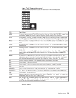
LED MEM CPU PCI A PCI B PCI C VRM DASD SP PS1 PS2 PS3 NON-RED OVERSPEC NMI TEMP FAN Light Path Diagnostics panel The Light Path Diagnostics LEDs are described in the following table. MEM PS1 CPU PS2 PCI A PS3 PCI B NON PCI C OVER VRM NMI DASD TEMP SP FAN REMIND Description A memory failure occurred. This LED is turned on when any of the Light Path LEDs located near the memory (DIMM) are turned on by the integrated system management processor. A CPU failure occurred. This LED is turned on when either of the two Light Path LEDs located near the appropriate CPU socket is turned on by the integrated system management processor. Error occurred on an adapter in PCI slot 1 or on one of the PCI devices integrated on the system board. Error occurred on an adapter in PCI slot 2 or 3 or on one of the PCI devices integrated on the system board. Error occurred on an adapter in PCI slot 4 or 5 or on one of the PCI devices integrated on the system board. A VRM failure occurred. This LED is turned on by the hardware when either of the two Light Path LEDs located near the appropriate VRM is turned on by the integrated system management processor. System board or SCSI hot-swap hard disk drive failure, hard disk drive removed from either standard or optional expansion hot-swap bay DASD backplane, or hard disk drive temperature has exceeded maximum limit (in this case, the TEMP and System error LEDs will be lit). An error has been detected in the integrated system management processor. Power supply 1 failure or removed. Power supply 2 failure or removed (only active when 2nd power supply is installed). Not used. Server power supplies are no longer redundant with two power supplies installed. The system has approached 95% of the power capabilities of the installed power-supply units. Nonmaskable interrupt occurred. System temperature exceeded maximum limit. Other LEDs will be on to identify the area of over temperature (such as CPUx, CPU, DASD LEDs). Fan failure, or fan is operating slowly or has been removed. This LED is turned on when any of the Light Path LEDs mounted directly on the fan assemblies or near the CPU sockets are turned on by the integrated system management processor. Remind Button Installing options 39
-
 1
1 -
2
-
3
-
4
-
5
-
6
-
7
-
8
-
9
-
10
-
11
-
12
-
13
-
14
-
15
-
16
-
17
-
18
-
19
-
20
-
21
-
22
-
23
-
24
-
25
-
26
-
27
-
28
-
29
-
30
-
31
-
32
-
33
-
34
-
35
-
36
-
37
-
38
-
39
-
40
-
41
-
42
-
43
-
 44
44 -
 45
45 -
 46
46 -
 47
47 -
 48
48 -
 49
49 -
 50
50 -
 51
51 -
 52
52 -
 53
53 -
 54
54 -
55
-
56
-
57
-
58
-
59
-
60
-
61
-
62
-
63
-
64
-
65
-
66
-
67
-
68
-
69
-
70
-
71
-
72
-
73
-
74
-
75
-
76
-
77
-
78
-
79
-
80
-
81
-
82
-
83
-
84
-
85
-
86
-
87
-
88
-
89
-
90
-
91
-
92
-
93
-
94
-
95
-
96
-
97
-
98
-
99
-
100
-
101
-
102
-
103
-
104
-
105
-
106
-
107
-
108
-
109
-
110
-
111
-
112
-
113
-
114
-
115
-
116
-
117
-
118
-
119
-
120
-
121
-
122
-
123
-
124
-
125
-
126
-
127
-
128
-
129
-
130
-
131
-
132
-
133
-
134
-
135
-
136
-
137
-
138
-
139
-
140
-
141
-
142
-
143
-
144
-
145
-
146
-
147
-
148
-
149
-
150
-
151
-
152
-
153
-
154
-
155
-
156
 |
 |
