ZyXEL ES-2108PWR User Guide - Page 40
Be careful to avoid damaging pipes or cables located inside the wall when, drilling holes for
 |
View all ZyXEL ES-2108PWR manuals
Add to My Manuals
Save this manual to your list of manuals |
Page 40 highlights
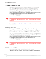
Chapter 2 Hardware Installation and Connection 2 Drill two holes for the screws (not included). Make sure the distance between the centers of the holes matches what is listed in the product specifications appendix. 1 Be careful to avoid damaging pipes or cables located inside the wall when drilling holes for the screws. 3 Do not screw the screws all the way into the wall. Leave a small gap of about 0.5 cm between the heads of the screws and the wall. 4 Make sure the screws are snugly fastened to the wall. They need to hold the weight of the Switch with the connection cables. 5 Align the holes on the back of the Switch with the screws on the wall. Hang the Switch on the screws. Figure 9 Wall-mounting Example 40 ES-2108 Series User's Guide
-
 1
1 -
2
-
3
-
4
-
5
-
6
-
7
-
8
-
9
-
10
-
11
-
12
-
13
-
14
-
15
-
16
-
17
-
18
-
19
-
20
-
21
-
22
-
23
-
24
-
25
-
26
-
27
-
28
-
29
-
30
-
31
-
32
-
33
-
34
-
 35
35 -
 36
36 -
 37
37 -
 38
38 -
 39
39 -
 40
40 -
 41
41 -
 42
42 -
 43
43 -
 44
44 -
 45
45 -
46
-
47
-
48
-
49
-
50
-
51
-
52
-
53
-
54
-
55
-
56
-
57
-
58
-
59
-
60
-
61
-
62
-
63
-
64
-
65
-
66
-
67
-
68
-
69
-
70
-
71
-
72
-
73
-
74
-
75
-
76
-
77
-
78
-
79
-
80
-
81
-
82
-
83
-
84
-
85
-
86
-
87
-
88
-
89
-
90
-
91
-
92
-
93
-
94
-
95
-
96
-
97
-
98
-
99
-
100
-
101
-
102
-
103
-
104
-
105
-
106
-
107
-
108
-
109
-
110
-
111
-
112
-
113
-
114
-
115
-
116
-
117
-
118
-
119
-
120
-
121
-
122
-
123
-
124
-
125
-
126
-
127
-
128
-
129
-
130
-
131
-
132
-
133
-
134
-
135
-
136
-
137
-
138
-
139
-
140
-
141
-
142
-
143
-
144
-
145
-
146
-
147
-
148
-
149
-
150
-
151
-
152
-
153
-
154
-
155
-
156
-
157
-
158
-
159
-
160
-
161
-
162
-
163
-
164
-
165
-
166
-
167
-
168
-
169
-
170
-
171
-
172
-
173
-
174
-
175
-
176
-
177
-
178
-
179
-
180
-
181
-
182
-
183
-
184
-
185
-
186
-
187
-
188
-
189
-
190
-
191
-
192
-
193
-
194
-
195
-
196
-
197
-
198
-
199
-
200
-
201
-
202
-
203
-
204
-
205
-
206
-
207
-
208
-
209
-
210
-
211
-
212
-
213
-
214
-
215
-
216
-
217
-
218
-
219
-
220
-
221
-
222
-
223
-
224
-
225
-
226
-
227
-
228
-
229
-
230
-
231
-
232
-
233
-
234
-
235
-
236
-
237
-
238
-
239
-
240
-
241
-
242
-
243
-
244
-
245
-
246
-
247
-
248
-
249
-
250
-
251
-
252
-
253
-
254
-
255
-
256
-
257
-
258
-
259
-
260
-
261
-
262
-
263
-
264
-
265
-
266
-
267
-
268
-
269
-
270
-
271
-
272
-
273
-
274
-
275
-
276
-
277
-
278
-
279
-
280
-
281
-
282
-
283
-
284
 |
 |
Chapter 2 Hardware Installation and Connection
ES-2108 Series User’s Guide
40
2
Drill two holes for the screws (not included). Make sure the distance between the centers
of the holes matches what is listed in the product specifications appendix.
Be careful to avoid damaging pipes or cables located inside the wall when
drilling holes for the screws.
3
Do not screw the screws all the way into the wall. Leave a small gap of about 0.5 cm
between the heads of the screws and the wall.
4
Make sure the screws are snugly fastened to the wall. They need to hold the weight of
the Switch with the connection cables.
5
Align the holes on the back of the Switch with the screws on the wall. Hang the Switch
on the screws.
Figure 9
Wall-mounting Example