ZyXEL ES-2108PWR User Guide - Page 80
Port Setup
 |
View all ZyXEL ES-2108PWR manuals
Add to My Manuals
Save this manual to your list of manuals |
Page 80 highlights
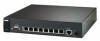
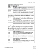
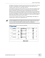
Chapter 7 Basic Setting Table 12 Basic Setting > IP Setup (continued) LABEL DESCRIPTION Default Enter the IP address of the default outgoing gateway in dotted decimal notation, for Gateway example 192.168.0.254 VID Enter the VLAN identification number associated with the IP address. This is the VLAN ID of the CPU and is used for management only. The default is "1". All ports, by default, are fixed members of this "management VLAN" in order to manage the device from any port. If a port is not a member of this VLAN, then users on that port cannot access the device. To access the Switch make sure the port that you are connected to is a member of Management VLAN. Apply Click Apply to save your changes to the Switch's run-time memory. The Switch loses these changes if it is turned off or loses power, so use the Save link on the top navigation panel to save your changes to the non-volatile memory when you are done configuring. Cancel Click Cancel to reset the fields to your previous configuration. Management Configure the fields to set additional management IP address. IP Addresses IP Address Enter the IP address for managing the Switch by the members of the VLAN specified in the VID field below. IP Subnet Mask Enter the IP subnet mask in dotted decimal notation. For example, 255.255.255.0. VID Enter the VLAN identification number. Default Gateway Enter the IP address of the default outgoing gateway in dotted decimal notation, for example 192.168.1.254 Add Click Add to save your changes to the Switch's run-time memory. The Switch loses these changes if it is turned off or loses power, so use the Save link on the top navigation panel to save your changes to the non-volatile memory when you are done configuring. Cancel Click Cancel to reset the fields to your previous configuration. Index This field displays the index number of an entry. IP Address This field displays the management IP address of the Switch. IP Subnet Mask This field displays the subnet mask of the Switch. VID This field displays the VLAN identification number of the network. Default Gateway This field displays the default gateway of the Switch. Delete Click Delete to remove the selected entry from the summary table. Cancel Click Cancel to clear the Delete check boxes. 7.7 Port Setup Ethernet port connections can be in half-duplex or full-duplex mode. Full-duplex refers to a device's ability to send and receive simultaneously, while half-duplex indicates that traffic can flow in only one direction at a time. The Ethernet port must use the same speed or duplex mode setting as the peer Ethernet port in order to connect. 80 ES-2108 Series User's Guide
-
 1
1 -
2
-
3
-
4
-
5
-
6
-
7
-
8
-
9
-
10
-
11
-
12
-
13
-
14
-
15
-
16
-
17
-
18
-
19
-
20
-
21
-
22
-
23
-
24
-
25
-
26
-
27
-
28
-
29
-
30
-
31
-
32
-
33
-
34
-
35
-
36
-
37
-
38
-
39
-
40
-
41
-
42
-
43
-
44
-
45
-
46
-
47
-
48
-
49
-
50
-
51
-
52
-
53
-
54
-
55
-
56
-
57
-
58
-
59
-
60
-
61
-
62
-
63
-
64
-
65
-
66
-
67
-
68
-
69
-
70
-
71
-
72
-
73
-
74
-
 75
75 -
 76
76 -
 77
77 -
 78
78 -
 79
79 -
 80
80 -
 81
81 -
 82
82 -
 83
83 -
 84
84 -
 85
85 -
86
-
87
-
88
-
89
-
90
-
91
-
92
-
93
-
94
-
95
-
96
-
97
-
98
-
99
-
100
-
101
-
102
-
103
-
104
-
105
-
106
-
107
-
108
-
109
-
110
-
111
-
112
-
113
-
114
-
115
-
116
-
117
-
118
-
119
-
120
-
121
-
122
-
123
-
124
-
125
-
126
-
127
-
128
-
129
-
130
-
131
-
132
-
133
-
134
-
135
-
136
-
137
-
138
-
139
-
140
-
141
-
142
-
143
-
144
-
145
-
146
-
147
-
148
-
149
-
150
-
151
-
152
-
153
-
154
-
155
-
156
-
157
-
158
-
159
-
160
-
161
-
162
-
163
-
164
-
165
-
166
-
167
-
168
-
169
-
170
-
171
-
172
-
173
-
174
-
175
-
176
-
177
-
178
-
179
-
180
-
181
-
182
-
183
-
184
-
185
-
186
-
187
-
188
-
189
-
190
-
191
-
192
-
193
-
194
-
195
-
196
-
197
-
198
-
199
-
200
-
201
-
202
-
203
-
204
-
205
-
206
-
207
-
208
-
209
-
210
-
211
-
212
-
213
-
214
-
215
-
216
-
217
-
218
-
219
-
220
-
221
-
222
-
223
-
224
-
225
-
226
-
227
-
228
-
229
-
230
-
231
-
232
-
233
-
234
-
235
-
236
-
237
-
238
-
239
-
240
-
241
-
242
-
243
-
244
-
245
-
246
-
247
-
248
-
249
-
250
-
251
-
252
-
253
-
254
-
255
-
256
-
257
-
258
-
259
-
260
-
261
-
262
-
263
-
264
-
265
-
266
-
267
-
268
-
269
-
270
-
271
-
272
-
273
-
274
-
275
-
276
-
277
-
278
-
279
-
280
-
281
-
282
-
283
-
284
 |
 |