ZyXEL ES-2108PWR User Guide - Page 73
General Setup
 |
View all ZyXEL ES-2108PWR manuals
Add to My Manuals
Save this manual to your list of manuals |
Page 73 highlights
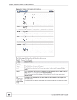
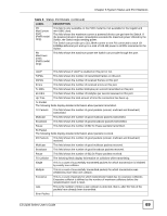
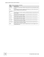
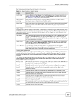
Chapter 7 Basic Setting Table 9 Basic Setting > System Info (continued) LABEL DESCRIPTION Hardware Monitor (The following hardware monitoring information is only available on the PWR model.) Temperature Unit The Switch has temperature sensors that are capable of detecting and reporting if the temperature rises above the threshold. You may choose the temperature unit (Centigrade or Fahrenheit) in this field. Temperature CPU, MAC and LOCAL refer to the location of the temperature sensors on the Switch printed circuit board. Current This field displays the current temperature measured at this sensor. MAX This field displays the maximum temperature measured at this sensor. MIN This field displays the minimum temperature measured at this sensor. Threshold This field displays the upper temperature limit at this sensor. Status This field displays Normal for temperatures below the threshold and Error for those above. Fan speed (RPM) A properly functioning fan is an essential component (along with a sufficiently ventilated, cool operating environment) in order for the device to stay within the temperature threshold. Each fan has a sensor that is capable of detecting and reporting if the fan speed falls below the threshold shown. Current This field displays this fan's current speed in Revolutions Per Minute (RPM). MAX This field displays this fan's maximum speed measured in Revolutions Per Minute (RPM). MIN This field displays this fan's minimum speed measured in Revolutions Per Minute (RPM). "
-
 1
1 -
2
-
3
-
4
-
5
-
6
-
7
-
8
-
9
-
10
-
11
-
12
-
13
-
14
-
15
-
16
-
17
-
18
-
19
-
20
-
21
-
22
-
23
-
24
-
25
-
26
-
27
-
28
-
29
-
30
-
31
-
32
-
33
-
34
-
35
-
36
-
37
-
38
-
39
-
40
-
41
-
42
-
43
-
44
-
45
-
46
-
47
-
48
-
49
-
50
-
51
-
52
-
53
-
54
-
55
-
56
-
57
-
58
-
59
-
60
-
61
-
62
-
63
-
64
-
65
-
66
-
67
-
 68
68 -
 69
69 -
 70
70 -
 71
71 -
 72
72 -
 73
73 -
 74
74 -
 75
75 -
 76
76 -
 77
77 -
 78
78 -
79
-
80
-
81
-
82
-
83
-
84
-
85
-
86
-
87
-
88
-
89
-
90
-
91
-
92
-
93
-
94
-
95
-
96
-
97
-
98
-
99
-
100
-
101
-
102
-
103
-
104
-
105
-
106
-
107
-
108
-
109
-
110
-
111
-
112
-
113
-
114
-
115
-
116
-
117
-
118
-
119
-
120
-
121
-
122
-
123
-
124
-
125
-
126
-
127
-
128
-
129
-
130
-
131
-
132
-
133
-
134
-
135
-
136
-
137
-
138
-
139
-
140
-
141
-
142
-
143
-
144
-
145
-
146
-
147
-
148
-
149
-
150
-
151
-
152
-
153
-
154
-
155
-
156
-
157
-
158
-
159
-
160
-
161
-
162
-
163
-
164
-
165
-
166
-
167
-
168
-
169
-
170
-
171
-
172
-
173
-
174
-
175
-
176
-
177
-
178
-
179
-
180
-
181
-
182
-
183
-
184
-
185
-
186
-
187
-
188
-
189
-
190
-
191
-
192
-
193
-
194
-
195
-
196
-
197
-
198
-
199
-
200
-
201
-
202
-
203
-
204
-
205
-
206
-
207
-
208
-
209
-
210
-
211
-
212
-
213
-
214
-
215
-
216
-
217
-
218
-
219
-
220
-
221
-
222
-
223
-
224
-
225
-
226
-
227
-
228
-
229
-
230
-
231
-
232
-
233
-
234
-
235
-
236
-
237
-
238
-
239
-
240
-
241
-
242
-
243
-
244
-
245
-
246
-
247
-
248
-
249
-
250
-
251
-
252
-
253
-
254
-
255
-
256
-
257
-
258
-
259
-
260
-
261
-
262
-
263
-
264
-
265
-
266
-
267
-
268
-
269
-
270
-
271
-
272
-
273
-
274
-
275
-
276
-
277
-
278
-
279
-
280
-
281
-
282
-
283
-
284
 |
 |