ZyXEL ES-2108PWR User Guide - Page 96
VLAN, ES-2108 Series User's Guide, Advanced Application > VLAN: Port Based VLAN Setup
 |
View all ZyXEL ES-2108PWR manuals
Add to My Manuals
Save this manual to your list of manuals |
Page 96 highlights
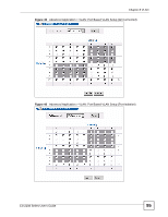
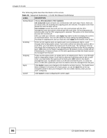
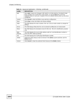
Chapter 8 VLAN The following table describes the labels in this screen. Table 19 Advanced Application > VLAN: Port Based VLAN Setup LABEL DESCRIPTION Setting Wizard Choose All connected or Port isolation. All connected means all ports can communicate with each other, that is, there are no virtual LANs. All incoming and outgoing ports are selected. This option is the most flexible but also the least secure. Port isolation means that each port can only communicate with the CPU management port and cannot communicate with each other. All incoming ports are selected while only the CPU outgoing port is selected. This option is the most limiting but also the most secure. After you make your selection, click Apply (top right of screen) to display the screens as mentioned above. You can still customize these settings by adding/deleting incoming or outgoing ports, but you must also click Apply at the bottom of the screen. Incoming These are the ingress ports; an ingress port is an incoming port, that is, a port through which a data packet enters. If you wish to allow two subscriber ports to talk to each other, you must define the ingress port for both ports. The numbers in the top row denote the incoming port for the corresponding port listed on the left (its outgoing port). CPU refers to the Switch management port. By default it forms a VLAN with all Ethernet ports. If it does not form a VLAN with a particular port then the Switch cannot be managed from that port. Outgoing These are the egress ports; an egress port is an outgoing port, that is, a port through which a data packet leaves. If you wish to allow two subscriber ports to talk to each other, you must define the egress port for both ports. CPU refers to the Switch management port. By default it forms a VLAN with all Ethernet ports. If it does not form a VLAN with a particular port then the Switch cannot be managed from that port. Apply Click Apply to save your changes to the Switch's run-time memory. The Switch loses these changes if it is turned off or loses power, so use the Save link on the top navigation panel to save your changes to the non-volatile memory when you are done configuring. Cancel Click Cancel to start configuring the screen again. 96 ES-2108 Series User's Guide
-
 1
1 -
2
-
3
-
4
-
5
-
6
-
7
-
8
-
9
-
10
-
11
-
12
-
13
-
14
-
15
-
16
-
17
-
18
-
19
-
20
-
21
-
22
-
23
-
24
-
25
-
26
-
27
-
28
-
29
-
30
-
31
-
32
-
33
-
34
-
35
-
36
-
37
-
38
-
39
-
40
-
41
-
42
-
43
-
44
-
45
-
46
-
47
-
48
-
49
-
50
-
51
-
52
-
53
-
54
-
55
-
56
-
57
-
58
-
59
-
60
-
61
-
62
-
63
-
64
-
65
-
66
-
67
-
68
-
69
-
70
-
71
-
72
-
73
-
74
-
75
-
76
-
77
-
78
-
79
-
80
-
81
-
82
-
83
-
84
-
85
-
86
-
87
-
88
-
89
-
90
-
 91
91 -
 92
92 -
 93
93 -
 94
94 -
 95
95 -
 96
96 -
 97
97 -
 98
98 -
 99
99 -
 100
100 -
 101
101 -
102
-
103
-
104
-
105
-
106
-
107
-
108
-
109
-
110
-
111
-
112
-
113
-
114
-
115
-
116
-
117
-
118
-
119
-
120
-
121
-
122
-
123
-
124
-
125
-
126
-
127
-
128
-
129
-
130
-
131
-
132
-
133
-
134
-
135
-
136
-
137
-
138
-
139
-
140
-
141
-
142
-
143
-
144
-
145
-
146
-
147
-
148
-
149
-
150
-
151
-
152
-
153
-
154
-
155
-
156
-
157
-
158
-
159
-
160
-
161
-
162
-
163
-
164
-
165
-
166
-
167
-
168
-
169
-
170
-
171
-
172
-
173
-
174
-
175
-
176
-
177
-
178
-
179
-
180
-
181
-
182
-
183
-
184
-
185
-
186
-
187
-
188
-
189
-
190
-
191
-
192
-
193
-
194
-
195
-
196
-
197
-
198
-
199
-
200
-
201
-
202
-
203
-
204
-
205
-
206
-
207
-
208
-
209
-
210
-
211
-
212
-
213
-
214
-
215
-
216
-
217
-
218
-
219
-
220
-
221
-
222
-
223
-
224
-
225
-
226
-
227
-
228
-
229
-
230
-
231
-
232
-
233
-
234
-
235
-
236
-
237
-
238
-
239
-
240
-
241
-
242
-
243
-
244
-
245
-
246
-
247
-
248
-
249
-
250
-
251
-
252
-
253
-
254
-
255
-
256
-
257
-
258
-
259
-
260
-
261
-
262
-
263
-
264
-
265
-
266
-
267
-
268
-
269
-
270
-
271
-
272
-
273
-
274
-
275
-
276
-
277
-
278
-
279
-
280
-
281
-
282
-
283
-
284
 |
 |