ZyXEL ES-2108PWR User Guide - Page 77
LABEL, DESCRIPTION, Port Based, VLAN Setup, Leave, Leave All, Join Period, Join Time, Leave Period, - 8 port layer
 |
View all ZyXEL ES-2108PWR manuals
Add to My Manuals
Save this manual to your list of manuals |
Page 77 highlights
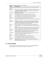
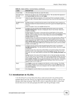
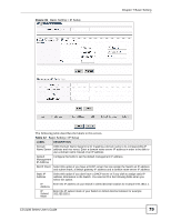
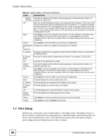
Chapter 7 Basic Setting The following table describes the labels in this screen. Table 11 Basic Setting > Switch Setup LABEL DESCRIPTION VLAN Type Choose 802.1Q or Port Based. The VLAN Setup screen changes depending on whether you choose 802.1Q VLAN type or Port Based VLAN type in this screen. See Chapter 8 on page 87 for more information. MAC Address MAC address learning reduces outgoing traffic broadcasts. For MAC address Learning learning to occur on a port, the port must be active. Aging Time Enter a time from 10 to 3000 seconds. This is how long all dynamically learned MAC addresses remain in the MAC address table before they age out (and must be relearned). GARP Timer: Switches join VLANs by making a declaration. A declaration is made by issuing a Join message using GARP. Declarations are withdrawn by issuing a Leave message. A Leave All message terminates all registrations. GARP timers set declaration timeout values. See the chapter on VLAN setup for more background information. Join Timer Join Timer sets the duration of the Join Period timer for GVRP in milliseconds. Each port has a Join Period timer. The allowed Join Time range is between 100 and 65535 milliseconds; the default is 200 milliseconds. See the chapter on VLAN setup for more background information. Leave Timer Leave Time sets the duration of the Leave Period timer for GVRP in milliseconds. Each port has a single Leave Period timer. Leave Time must be two times larger than Join Timer; the default is 600 milliseconds. Leave All Timer Leave All Timer sets the duration of the Leave All Period timer for GVRP in milliseconds. Each port has a single Leave All Period timer. Leave All Timer must be larger than Leave Timer; the default is 10000 milliseconds. Priority Queue Assignment IEEE 802.1p defines up to eight separate traffic types by inserting a tag into a MAC-layer frame that contains bits to define class of service. Frames without an explicit priority tag are given the default priority of the ingress port. Use the following fields to configure the priority level-to-physical queue mapping. The Switch has eight physical queues that you can map to the eight priority levels. On the Switch, traffic assigned to higher index queues gets through faster while traffic in lower index queues is dropped if the network is congested. Priority Level (The following descriptions are based on the traffic types defined in the IEEE 802.1d standard (which incorporates the 802.1p). Level 7 Typically used for network control traffic such as router configuration messages. Level 6 Typically used for voice traffic that is especially sensitive to jitter (jitter is the variations in delay). Level 5 Typically used for video that consumes high bandwidth and is sensitive to jitter. Level 4 Typically used for controlled load, latency-sensitive traffic such as SNA (Systems Network Architecture) transactions. Level 3 Typically used for "excellent effort" or better than best effort and would include important business traffic that can tolerate some delay. Level 2 This is for "spare bandwidth". Level 1 This is typically used for non-critical "background" traffic such as bulk transfers that are allowed but that should not affect other applications and users. Level 0 Typically used for best-effort traffic. ES-2108 Series User's Guide 77
-
 1
1 -
2
-
3
-
4
-
5
-
6
-
7
-
8
-
9
-
10
-
11
-
12
-
13
-
14
-
15
-
16
-
17
-
18
-
19
-
20
-
21
-
22
-
23
-
24
-
25
-
26
-
27
-
28
-
29
-
30
-
31
-
32
-
33
-
34
-
35
-
36
-
37
-
38
-
39
-
40
-
41
-
42
-
43
-
44
-
45
-
46
-
47
-
48
-
49
-
50
-
51
-
52
-
53
-
54
-
55
-
56
-
57
-
58
-
59
-
60
-
61
-
62
-
63
-
64
-
65
-
66
-
67
-
68
-
69
-
70
-
71
-
 72
72 -
 73
73 -
 74
74 -
 75
75 -
 76
76 -
 77
77 -
 78
78 -
 79
79 -
 80
80 -
 81
81 -
 82
82 -
83
-
84
-
85
-
86
-
87
-
88
-
89
-
90
-
91
-
92
-
93
-
94
-
95
-
96
-
97
-
98
-
99
-
100
-
101
-
102
-
103
-
104
-
105
-
106
-
107
-
108
-
109
-
110
-
111
-
112
-
113
-
114
-
115
-
116
-
117
-
118
-
119
-
120
-
121
-
122
-
123
-
124
-
125
-
126
-
127
-
128
-
129
-
130
-
131
-
132
-
133
-
134
-
135
-
136
-
137
-
138
-
139
-
140
-
141
-
142
-
143
-
144
-
145
-
146
-
147
-
148
-
149
-
150
-
151
-
152
-
153
-
154
-
155
-
156
-
157
-
158
-
159
-
160
-
161
-
162
-
163
-
164
-
165
-
166
-
167
-
168
-
169
-
170
-
171
-
172
-
173
-
174
-
175
-
176
-
177
-
178
-
179
-
180
-
181
-
182
-
183
-
184
-
185
-
186
-
187
-
188
-
189
-
190
-
191
-
192
-
193
-
194
-
195
-
196
-
197
-
198
-
199
-
200
-
201
-
202
-
203
-
204
-
205
-
206
-
207
-
208
-
209
-
210
-
211
-
212
-
213
-
214
-
215
-
216
-
217
-
218
-
219
-
220
-
221
-
222
-
223
-
224
-
225
-
226
-
227
-
228
-
229
-
230
-
231
-
232
-
233
-
234
-
235
-
236
-
237
-
238
-
239
-
240
-
241
-
242
-
243
-
244
-
245
-
246
-
247
-
248
-
249
-
250
-
251
-
252
-
253
-
254
-
255
-
256
-
257
-
258
-
259
-
260
-
261
-
262
-
263
-
264
-
265
-
266
-
267
-
268
-
269
-
270
-
271
-
272
-
273
-
274
-
275
-
276
-
277
-
278
-
279
-
280
-
281
-
282
-
283
-
284
 |
 |