Brother International HS-5300 Service Manual - Page 23
Brother International HS-5300 Manual
 |
View all Brother International HS-5300 manuals
Add to My Manuals
Save this manual to your list of manuals |
Page 23 highlights
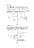
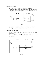
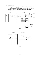
1.3.1. Features The circuit on the control PCB is classified into the following three sections. • Image processing Converts the image data received from the centronics parallel interface into the bit map. • Print head control Sends the bitmap data, which is converted from the image data, to the head and generates the ink jet timing. • Engine control Controls the motors and heaters, and receives the input data from the sensors. 1.3.2 Image Processing (1) Main CPU The IDT79R3051-20J, a 32bits RISC processor, is used to process the image data. The main CPU operates at a clock speed of 19.6608 MHz. (2) ASIC1 The HG51CS265FD is used as the ASIC to control the CPU peripheral and centronics interface circuits.. (3) ROM Two 16Mbits (1048576word x 16bits) mask ROMs (or flash ROMs) are used to store the program for the main CPU and font data. A ROM with an access time of 120 nsec. or faster must be used. (4) DRAM Four 16Mbits (1048576word x 16bits) DRAMs (TC5118160AJ-7 or equivalent) are used as a CPU work area and image data receiving buffer. A DRAM with an access time of 80 nsec. or faster must be used. The data in the DRAMs is refreshed based on the CBR (CAS before RAS) system. (5) SIMM Up to two 72pin SIMMs can be additionally installed to expand the memory capacity up to 72MB. One or two SIMMs selected from 1, 2, 4, 8, 16, and 32MB can be installed. When expanding the memory, install the SIMMs in SLOT 1 and SLOT 2 in that order. Additionally, when installing two SIMMs having a different capacity, the SIMM with a larger capacity must be installed in SLOT 1. The SIMM must have the following specifications: Type: Access Time: Capacity: Height 72 pin and 32 bit or 36 bit output 80 nsec. or less 1, 2, 4, 8, 16 or 32 Mbytes 38 mm (1.5 inches) or less 11-4
-
 1
1 -
2
-
3
-
4
-
5
-
6
-
7
-
8
-
9
-
10
-
11
-
12
-
13
-
14
-
15
-
16
-
17
-
 18
18 -
 19
19 -
 20
20 -
 21
21 -
 22
22 -
 23
23 -
 24
24 -
 25
25 -
 26
26 -
 27
27 -
 28
28 -
29
-
30
-
31
-
32
-
33
-
34
-
35
-
36
-
37
-
38
-
39
-
40
-
41
-
42
-
43
-
44
-
45
-
46
-
47
-
48
-
49
-
50
-
51
-
52
-
53
-
54
-
55
-
56
-
57
-
58
-
59
-
60
-
61
-
62
-
63
-
64
-
65
-
66
-
67
-
68
-
69
-
70
-
71
-
72
-
73
-
74
-
75
-
76
-
77
-
78
-
79
-
80
-
81
-
82
-
83
-
84
-
85
-
86
-
87
-
88
-
89
-
90
-
91
-
92
-
93
-
94
-
95
-
96
-
97
-
98
-
99
-
100
-
101
-
102
-
103
-
104
-
105
-
106
-
107
-
108
-
109
-
110
-
111
-
112
-
113
-
114
-
115
-
116
-
117
-
118
-
119
-
120
-
121
-
122
-
123
-
124
-
125
-
126
-
127
-
128
-
129
-
130
-
131
-
132
-
133
-
134
-
135
-
136
-
137
-
138
-
139
-
140
-
141
-
142
-
143
-
144
-
145
-
146
-
147
-
148
-
149
-
150
-
151
-
152
-
153
-
154
-
155
-
156
-
157
-
158
-
159
-
160
-
161
-
162
-
163
-
164
-
165
-
166
-
167
-
168
 |
 |
