Brother International HS-5300 Service Manual - Page 31
Drive, Circuit, drive, circuit, sends, print, driver, generates, pulses, head., connects, carriage,
 |
View all Brother International HS-5300 manuals
Add to My Manuals
Save this manual to your list of manuals |
Page 31 highlights
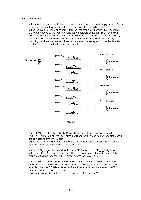
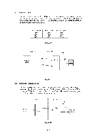
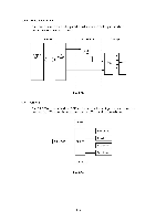
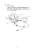
1.4.9 Head Drive Circuit The head drive circuit sends the print data to the driver IC for the print head and generates pulses to drive the head. Main PCB Driver PCB i Carriage Engine < CPU Jet > ASIC3 Head Driver CR PCB Head Fig. 2.13 1.5 CR PCB The CR PCB connects the driver PCB and the head on the carriage, the head heater, the encoder, the PW sensor, the tank heater and the LOIS circuit as shown below. Head Driver PCB CR PCB LOIS Circuit Head Heater Encoder PW Sensor Tank Heater Fig. 2.14 11-12
-
 1
1 -
2
-
3
-
4
-
5
-
6
-
7
-
8
-
9
-
10
-
11
-
12
-
13
-
14
-
15
-
16
-
17
-
18
-
19
-
20
-
21
-
22
-
23
-
24
-
25
-
 26
26 -
 27
27 -
 28
28 -
 29
29 -
 30
30 -
 31
31 -
 32
32 -
 33
33 -
 34
34 -
 35
35 -
 36
36 -
37
-
38
-
39
-
40
-
41
-
42
-
43
-
44
-
45
-
46
-
47
-
48
-
49
-
50
-
51
-
52
-
53
-
54
-
55
-
56
-
57
-
58
-
59
-
60
-
61
-
62
-
63
-
64
-
65
-
66
-
67
-
68
-
69
-
70
-
71
-
72
-
73
-
74
-
75
-
76
-
77
-
78
-
79
-
80
-
81
-
82
-
83
-
84
-
85
-
86
-
87
-
88
-
89
-
90
-
91
-
92
-
93
-
94
-
95
-
96
-
97
-
98
-
99
-
100
-
101
-
102
-
103
-
104
-
105
-
106
-
107
-
108
-
109
-
110
-
111
-
112
-
113
-
114
-
115
-
116
-
117
-
118
-
119
-
120
-
121
-
122
-
123
-
124
-
125
-
126
-
127
-
128
-
129
-
130
-
131
-
132
-
133
-
134
-
135
-
136
-
137
-
138
-
139
-
140
-
141
-
142
-
143
-
144
-
145
-
146
-
147
-
148
-
149
-
150
-
151
-
152
-
153
-
154
-
155
-
156
-
157
-
158
-
159
-
160
-
161
-
162
-
163
-
164
-
165
-
166
-
167
-
168
 |
 |

1.4.9
Head
Drive
Circuit
The
head
drive
circuit
sends
the
print
data
to
the
driver
IC
for
the
print
head
and
generates
pulses
to
drive
the
head.
Engine
CPU
Main
PCB
<
>
1.5
CR
PCB
Jet
ASIC3
Driver
PCB
i
Carriage
Head
Driver
Fig.
2.13
CR
PCB
PCB
Head
The
CR
PCB
connects
the
driver
PCB
and
the
head
on
the
carriage,
the
head
heater,
the
encoder,
the
PW
sensor,
the
tank
heater
and
the
LOIS
circuit
as
shown
below.
Driver
PCB
Head
CR
PCB
LOIS
Circuit
Fig.
2.14
Head
Heater
Encoder
PW
Sensor
Tank
Heater
11-12