Brother International HS-5300 Service Manual - Page 36
respective
 |
View all Brother International HS-5300 manuals
Add to My Manuals
Save this manual to your list of manuals |
Page 36 highlights
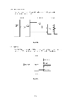
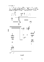
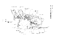
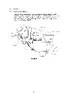
2.2.2 Structure of the Print Head (1) Front end Each Front end has 128 nozzles arranged in zigzags and fires the ink supplied from the Back end in drops. (2) Back end The Back end is connected to four (four-color) Front ends and supplies the hot melt ink in each color to the respective Front end. Solid ink in the ink supply unit is melted and supplied to the Front end through the ink circulation passage. • Ink melting tank The ink melting tank melts solid ink in the ink supply unit and supplies the melted ink to the ink tank. • Ink tank The ink tank keeps the hot melted ink and supplies it to the Front end when required. The ink tank has a two-chamber structure and also keeps the ink circulated by purging. The chambers are always connected to keep the same ink level in the two chambers. • Filter The filter eliminates foreign objects and air bubbles included in the hot melted ink supplied from the ink tank to the Front end, resulting in uniform and consistent ink firing from the Front end. • LOIS The LOIS detects a low ink level in the ink tanks. • Purge lever The purge lever functions when a purge is carried out. The purge lever disconnects the two chambers in the ink tank to create an ink circulation passage. • Ink circulation mechanism (purge mechanism) The ink circulation mechanism (purge mechanism) circulates the hot melted ink in the four individual colors that is remaining in the print head passage when the printer is turned ON or carrying out the purge from the control panel. When circulating the ink, it supplies new ink to the Front end through the filter and passes the old ink in the Front end (containing any air bubbles and foreign objects) to the ink tank in order to ensure optimal ink firing status. II-17
-
 1
1 -
2
-
3
-
4
-
5
-
6
-
7
-
8
-
9
-
10
-
11
-
12
-
13
-
14
-
15
-
16
-
17
-
18
-
19
-
20
-
21
-
22
-
23
-
24
-
25
-
26
-
27
-
28
-
29
-
30
-
 31
31 -
 32
32 -
 33
33 -
 34
34 -
 35
35 -
 36
36 -
 37
37 -
 38
38 -
 39
39 -
 40
40 -
 41
41 -
42
-
43
-
44
-
45
-
46
-
47
-
48
-
49
-
50
-
51
-
52
-
53
-
54
-
55
-
56
-
57
-
58
-
59
-
60
-
61
-
62
-
63
-
64
-
65
-
66
-
67
-
68
-
69
-
70
-
71
-
72
-
73
-
74
-
75
-
76
-
77
-
78
-
79
-
80
-
81
-
82
-
83
-
84
-
85
-
86
-
87
-
88
-
89
-
90
-
91
-
92
-
93
-
94
-
95
-
96
-
97
-
98
-
99
-
100
-
101
-
102
-
103
-
104
-
105
-
106
-
107
-
108
-
109
-
110
-
111
-
112
-
113
-
114
-
115
-
116
-
117
-
118
-
119
-
120
-
121
-
122
-
123
-
124
-
125
-
126
-
127
-
128
-
129
-
130
-
131
-
132
-
133
-
134
-
135
-
136
-
137
-
138
-
139
-
140
-
141
-
142
-
143
-
144
-
145
-
146
-
147
-
148
-
149
-
150
-
151
-
152
-
153
-
154
-
155
-
156
-
157
-
158
-
159
-
160
-
161
-
162
-
163
-
164
-
165
-
166
-
167
-
168
 |
 |
