Brother International HS-5300 Service Manual - Page 25
Brother International HS-5300 Manual
 |
View all Brother International HS-5300 manuals
Add to My Manuals
Save this manual to your list of manuals |
Page 25 highlights
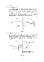
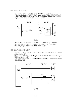
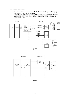
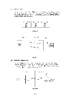
1.3.3 Print Head Control (1) ASIC 2 The MB87A133 is used as the ASIC to control the print head. The ASIC becomes the bus master instead of the main CPU during the print process and reads the converted image data from the DRAM based on the encoder signal and conditions sent from the main CPU and engine CPU. It also sends the data to the head and outputs the ink jet timing to the head drive circuit. This ASIC includes the following functions in addition to the print head control. • Extended I/O of the engine CPU • MIO interface • Timing generating circuit for the ink sensor • Carriage motor drive timing generating circuit 1.3.4 Engine Control (1) Engine CPU The µPD784021GC, a 16bit one-chip microprocessor, is used for the engine control. The engine CPU controls the following. • Carriage motor control • PA motor control • Fan motor control • Inputs and outputs from/to the operator panel • Heater control • Sensor inputs (2) ROM The HM27C101AG-12 or equivalent, a 1Mbit (131072-word x 8bits) EP-ROM, is used to store the program and data for the engine CPU. (3) EEPROM A 4Kbits EEPROM (X24C04 or equivalent) is used to store certain conditions. When the main CPU reads/writes the data from/to the EEPROM, the main CPU communicates with the engine CPU and the engine CPU actually reads and writes the data. 11-6
-
 1
1 -
2
-
3
-
4
-
5
-
6
-
7
-
8
-
9
-
10
-
11
-
12
-
13
-
14
-
15
-
16
-
17
-
18
-
19
-
 20
20 -
 21
21 -
 22
22 -
 23
23 -
 24
24 -
 25
25 -
 26
26 -
 27
27 -
 28
28 -
 29
29 -
 30
30 -
31
-
32
-
33
-
34
-
35
-
36
-
37
-
38
-
39
-
40
-
41
-
42
-
43
-
44
-
45
-
46
-
47
-
48
-
49
-
50
-
51
-
52
-
53
-
54
-
55
-
56
-
57
-
58
-
59
-
60
-
61
-
62
-
63
-
64
-
65
-
66
-
67
-
68
-
69
-
70
-
71
-
72
-
73
-
74
-
75
-
76
-
77
-
78
-
79
-
80
-
81
-
82
-
83
-
84
-
85
-
86
-
87
-
88
-
89
-
90
-
91
-
92
-
93
-
94
-
95
-
96
-
97
-
98
-
99
-
100
-
101
-
102
-
103
-
104
-
105
-
106
-
107
-
108
-
109
-
110
-
111
-
112
-
113
-
114
-
115
-
116
-
117
-
118
-
119
-
120
-
121
-
122
-
123
-
124
-
125
-
126
-
127
-
128
-
129
-
130
-
131
-
132
-
133
-
134
-
135
-
136
-
137
-
138
-
139
-
140
-
141
-
142
-
143
-
144
-
145
-
146
-
147
-
148
-
149
-
150
-
151
-
152
-
153
-
154
-
155
-
156
-
157
-
158
-
159
-
160
-
161
-
162
-
163
-
164
-
165
-
166
-
167
-
168
 |
 |
