Brother International HS-5300 Service Manual - Page 29
Drive, Circuit, LOIS_K, Thermistor, Detection, LOIS_C_D, LOIS_C, LOIS_M, LOIS_Y_D, LOIS_Y
 |
View all Brother International HS-5300 manuals
Add to My Manuals
Save this manual to your list of manuals |
Page 29 highlights
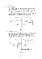
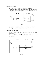
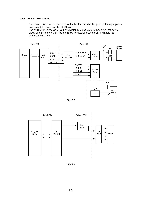
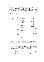
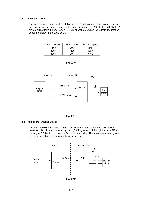
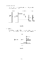
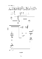
1.4.6 LOIS Circuit A thermistor is attached to the head ink tank for each color as an ink empty sensor. When a specified voltage level is applied to the thermistor, it heats up by itself. When the ink level in the ink tank is higher than the thermistor position, the ink absorbs the heat produced by the thermistor and the temperature at the thermistor rises slowly. When the ink level in the ink tank is below the thermistor position, the heat produced by the thermistor is not absorbed and the temperature at the thermistor rises fast. By watching the difference between these temperature increase speeds, it can be detected whether ink remains in the head ink tank or not. CPU .O-Ili. J ET ASIC 3 LOIS K D LOIS Drive Circuit LOIS_K LOIS Detection Circuit LOIS_C_D LOIS Drive Circuit LOIS_C LOIS Detection Circuit LOIS M D LOIS Drive Circuit LOIS_M LOIS Detection Circuit LOIS_Y_D LOIS Drive Circuit LOIS_Y LOIS Detection Circuit Fig. 2.9 K Head Ink Tank I iI Thermistor i I I C Head Ink Tank I i IThermistor ...) 1 I I M Head Ink Tank I 1 -1 I Thermistor i I I Y Head Ink Tank 1 r^, 1 Thermistor I I The Jet ASIC3 makes the LOIS_K_D signal level high at 32 msec. intervals. When the LOIS_K_D signal is high, the LOIS drive circuit applies a voltage to the thermistor to start the self-heating of the thermistor. When the LOIS detection circuit detects that the temperature at the thermistor reaches a specified level, the LOIS_K signal becomes low. As the LOIS_K signal becomes low, the Jet ASIC3 makes the LOIS_K_D signal low. When the LOIS_K_D signal is low, the LOIS drive circuit stops, the self heating of the thermistor finishes, and the LOIS_K signal returns to the high level. The CPU detects through the Jet ASIC3 whether the duration of the high level of the LOIS_K_D signal is shorter or longer than a specified length. When it is longer than a specified time, the CPU determines that ink still remains. When it is shorter, the CPU determines that the ink has run out. This procedure applies to the all head ink tanks for K, C, M, and Y. 11-10
-
 1
1 -
2
-
3
-
4
-
5
-
6
-
7
-
8
-
9
-
10
-
11
-
12
-
13
-
14
-
15
-
16
-
17
-
18
-
19
-
20
-
21
-
22
-
23
-
 24
24 -
 25
25 -
 26
26 -
 27
27 -
 28
28 -
 29
29 -
 30
30 -
 31
31 -
 32
32 -
 33
33 -
 34
34 -
35
-
36
-
37
-
38
-
39
-
40
-
41
-
42
-
43
-
44
-
45
-
46
-
47
-
48
-
49
-
50
-
51
-
52
-
53
-
54
-
55
-
56
-
57
-
58
-
59
-
60
-
61
-
62
-
63
-
64
-
65
-
66
-
67
-
68
-
69
-
70
-
71
-
72
-
73
-
74
-
75
-
76
-
77
-
78
-
79
-
80
-
81
-
82
-
83
-
84
-
85
-
86
-
87
-
88
-
89
-
90
-
91
-
92
-
93
-
94
-
95
-
96
-
97
-
98
-
99
-
100
-
101
-
102
-
103
-
104
-
105
-
106
-
107
-
108
-
109
-
110
-
111
-
112
-
113
-
114
-
115
-
116
-
117
-
118
-
119
-
120
-
121
-
122
-
123
-
124
-
125
-
126
-
127
-
128
-
129
-
130
-
131
-
132
-
133
-
134
-
135
-
136
-
137
-
138
-
139
-
140
-
141
-
142
-
143
-
144
-
145
-
146
-
147
-
148
-
149
-
150
-
151
-
152
-
153
-
154
-
155
-
156
-
157
-
158
-
159
-
160
-
161
-
162
-
163
-
164
-
165
-
166
-
167
-
168
 |
 |
