Brother International HS-5300 Service Manual - Page 26
Driver, 39/30V, Engine, PF_AN, PF_BN, ASIC3, PF_Hold, Motor, Drive, Circuit
 |
View all Brother International HS-5300 manuals
Add to My Manuals
Save this manual to your list of manuals |
Page 26 highlights
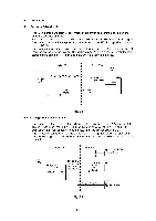
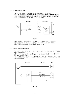
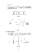
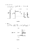
1.4 Driver PCB 1.4.1 PA Motor Drive Circuit The PA motor is a uni-polar stepper motor and is driven at a constant current by the specially designed drive IC. Each phase of the step motor is excited by the PF_A, PF_AN, PF_B and PF_BN signals. The current flowing in the stepper motor is switched by the PF_Hold signal output from the Jet ASIC3. The PA motor drive circuit controls the current flowing when the step motor is in the hold mode compared to when rotating. The circuit makes PF_Hold signal low when the motor starts rotating and the PF_Hold signal high when it is in the hold mode. Main PCB i Engine CPU PF_A, PF_AN, PF_B, PF_BN Driver PCB +39/30V 0 > PA Motor Drive Circuit P4 Jet < ASIC3 PF_Hold Fig. 2.3 1.4.2 Carriage Motor Drive Circuit The carriage motor is a DC motor and its speed is controlled by the PWM control of the engine CPU through the JET ASIC3 using the feed back signals (ENC_A and ENC_B) output from the linear encoder. Also it stops, when the interlock switch is off. The H bridge circuit is driven by the CR_Ql_ENA, CR_Q2_ENA, CR_Q3_ENA, and CR_Q4_ENA signals output from the Jet ASIC3 and the current flows to the DC motor to rotate it. Main PCB Driver PCB +52V P3 Interlock SW -- --o o--i Engine CPU PWTV1_Pulse N.- PWM Dir Jet ASIC3 CR_Q1_ENA CR_Q2_ENA i CR_Q3_ENA I CR_Q4_ENA Carriage P2 Motor > Drive Circuit ENC A, ENC_B CR PCB Encoder Fig. 2.4 11-7
-
 1
1 -
2
-
3
-
4
-
5
-
6
-
7
-
8
-
9
-
10
-
11
-
12
-
13
-
14
-
15
-
16
-
17
-
18
-
19
-
20
-
 21
21 -
 22
22 -
 23
23 -
 24
24 -
 25
25 -
 26
26 -
 27
27 -
 28
28 -
 29
29 -
 30
30 -
 31
31 -
32
-
33
-
34
-
35
-
36
-
37
-
38
-
39
-
40
-
41
-
42
-
43
-
44
-
45
-
46
-
47
-
48
-
49
-
50
-
51
-
52
-
53
-
54
-
55
-
56
-
57
-
58
-
59
-
60
-
61
-
62
-
63
-
64
-
65
-
66
-
67
-
68
-
69
-
70
-
71
-
72
-
73
-
74
-
75
-
76
-
77
-
78
-
79
-
80
-
81
-
82
-
83
-
84
-
85
-
86
-
87
-
88
-
89
-
90
-
91
-
92
-
93
-
94
-
95
-
96
-
97
-
98
-
99
-
100
-
101
-
102
-
103
-
104
-
105
-
106
-
107
-
108
-
109
-
110
-
111
-
112
-
113
-
114
-
115
-
116
-
117
-
118
-
119
-
120
-
121
-
122
-
123
-
124
-
125
-
126
-
127
-
128
-
129
-
130
-
131
-
132
-
133
-
134
-
135
-
136
-
137
-
138
-
139
-
140
-
141
-
142
-
143
-
144
-
145
-
146
-
147
-
148
-
149
-
150
-
151
-
152
-
153
-
154
-
155
-
156
-
157
-
158
-
159
-
160
-
161
-
162
-
163
-
164
-
165
-
166
-
167
-
168
 |
 |
