Brother International HS-5300 Service Manual - Page 9
configuration, diagram, shown, below., so!uoapa13
 |
View all Brother International HS-5300 manuals
Add to My Manuals
Save this manual to your list of manuals |
Page 9 highlights
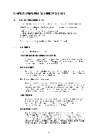
so!uoapa13 The configuration diagram is as shown below. MIO interface 11 (C2 Centronics interface Control PCB Paper eject sensor Driver PCB Switch panel Head Carriage PCB Encoder PW sensor Platen heater Media sensor Cam home position SW Maintenance PE SW PE sensor Option ROM SI M M (Occupied) SIMM (Vacant) Power suppyl° O O O Cover open SW unit Fan PS fan PA Carriage motor motor motor motor switch iii Solenoid
-
 1
1 -
2
-
3
-
 4
4 -
 5
5 -
 6
6 -
 7
7 -
 8
8 -
 9
9 -
 10
10 -
 11
11 -
 12
12 -
 13
13 -
 14
14 -
15
-
16
-
17
-
18
-
19
-
20
-
21
-
22
-
23
-
24
-
25
-
26
-
27
-
28
-
29
-
30
-
31
-
32
-
33
-
34
-
35
-
36
-
37
-
38
-
39
-
40
-
41
-
42
-
43
-
44
-
45
-
46
-
47
-
48
-
49
-
50
-
51
-
52
-
53
-
54
-
55
-
56
-
57
-
58
-
59
-
60
-
61
-
62
-
63
-
64
-
65
-
66
-
67
-
68
-
69
-
70
-
71
-
72
-
73
-
74
-
75
-
76
-
77
-
78
-
79
-
80
-
81
-
82
-
83
-
84
-
85
-
86
-
87
-
88
-
89
-
90
-
91
-
92
-
93
-
94
-
95
-
96
-
97
-
98
-
99
-
100
-
101
-
102
-
103
-
104
-
105
-
106
-
107
-
108
-
109
-
110
-
111
-
112
-
113
-
114
-
115
-
116
-
117
-
118
-
119
-
120
-
121
-
122
-
123
-
124
-
125
-
126
-
127
-
128
-
129
-
130
-
131
-
132
-
133
-
134
-
135
-
136
-
137
-
138
-
139
-
140
-
141
-
142
-
143
-
144
-
145
-
146
-
147
-
148
-
149
-
150
-
151
-
152
-
153
-
154
-
155
-
156
-
157
-
158
-
159
-
160
-
161
-
162
-
163
-
164
-
165
-
166
-
167
-
168
 |
 |

MIO
interface
11
(C2
Centronics
interface
Control
PCB
Option
ROM
SI
M M
(Occupied)
SIMM
(Vacant)
Paper
eject
sensor
Driver
PCB
Power
suppyl°
O
O
O
unit
Fan
PS
fan
PA
Carriage
motor
motor motor
motor
switch
ii
i
Cover
open
SW
Switch
panel
Carriage
PCB
Platen
heater
Media
sensor
Head
Encoder
PW
sensor
Cam
home
position SW
Maintenance
PE
SW
PE
sensor
Solenoid
The
configuration
diagram
is
as
shown
below.
so!uoapa13