Brother International HS-5300 Service Manual - Page 71
connector, Connector, holder, Screw, Setting, position
 |
View all Brother International HS-5300 manuals
Add to My Manuals
Save this manual to your list of manuals |
Page 71 highlights
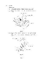
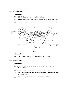
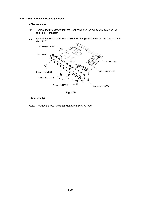
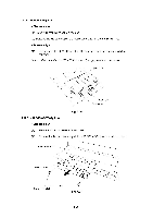
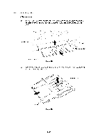
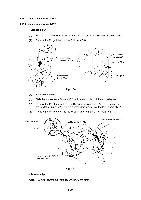
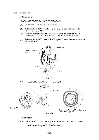
4.11.2 MIO Rails L and R (1) Slide the MID rails L and R out after pressing and releasing the hook of the MID rails L and R inserted into the hole on the Rear panel. MIO rail R I n MIO rail L Main PCB Fig. 4.23 (1) Match the hook of the MID rails with the key hole in the Connector PCB holder. By inserting the top into the bent part of the Rear panel and sliding the MID rails toward the Rear panel, press the MID rail until the hook is secured. 4.11.3 MIO Connector PCB ASSY (1) Remove the two screws from the bottom of the MID connector PCB to remove the MID connector PCB ASSY. Disconnect the connector by lifting it upwards to remove the whole MID connector PCB ASSY and the two screws from the Connector PCB holder. Main PCB MIO connector PCB ASSY .\ MIO connector PCB ASSY Connector PCB holder A f:, Screw, bind M3X6 i Screw, bind M3X6 Fig. 4.24 III-19 Setting position e t,
-
 1
1 -
2
-
3
-
4
-
5
-
6
-
7
-
8
-
9
-
10
-
11
-
12
-
13
-
14
-
15
-
16
-
17
-
18
-
19
-
20
-
21
-
22
-
23
-
24
-
25
-
26
-
27
-
28
-
29
-
30
-
31
-
32
-
33
-
34
-
35
-
36
-
37
-
38
-
39
-
40
-
41
-
42
-
43
-
44
-
45
-
46
-
47
-
48
-
49
-
50
-
51
-
52
-
53
-
54
-
55
-
56
-
57
-
58
-
59
-
60
-
61
-
62
-
63
-
64
-
65
-
 66
66 -
 67
67 -
 68
68 -
 69
69 -
 70
70 -
 71
71 -
 72
72 -
 73
73 -
 74
74 -
 75
75 -
 76
76 -
77
-
78
-
79
-
80
-
81
-
82
-
83
-
84
-
85
-
86
-
87
-
88
-
89
-
90
-
91
-
92
-
93
-
94
-
95
-
96
-
97
-
98
-
99
-
100
-
101
-
102
-
103
-
104
-
105
-
106
-
107
-
108
-
109
-
110
-
111
-
112
-
113
-
114
-
115
-
116
-
117
-
118
-
119
-
120
-
121
-
122
-
123
-
124
-
125
-
126
-
127
-
128
-
129
-
130
-
131
-
132
-
133
-
134
-
135
-
136
-
137
-
138
-
139
-
140
-
141
-
142
-
143
-
144
-
145
-
146
-
147
-
148
-
149
-
150
-
151
-
152
-
153
-
154
-
155
-
156
-
157
-
158
-
159
-
160
-
161
-
162
-
163
-
164
-
165
-
166
-
167
-
168
 |
 |
