Brother International HS-5300 Service Manual - Page 82
disconnect
 |
View all Brother International HS-5300 manuals
Add to My Manuals
Save this manual to your list of manuals |
Page 82 highlights
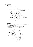
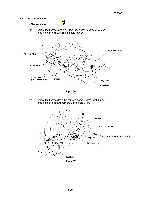
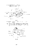
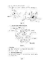
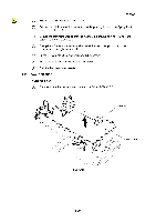
(2) Slightly lift the Driver PCB ASSY upwards and disconnect the FFC cables from the FFC connectors. FFC connector Driver PCB ASSY 4, FFC cable Fig. 4.43 (1) Insert the FFC cables into the connectors and hold the Driver PCB ASSY upside down. (2) Insert the cables into slot 1 and 2 securely. (3) Position the two bosses on the Main frame ASSY. (4) Insert the harnesses into the connectors securely. FFC cable 3 o 2 / c'e .------ O n N., No connection Power supply Power supply Fan P/S SW Panel Main PCB -0 4.i.,o, Paper feed sensor Maintenance paper empty sensor Media sensor (Light emitter) Media sensor (Light collector) Q-platen thermistor Fig. 4.44 ® No connection O Platen O Pre-platen O Solenoid B, C O Solenoid A 0 FAN / Platen O CI Cam home position sensor PA motor 0 Interlock SW 10 Carriage motor III-30
-
 1
1 -
2
-
3
-
4
-
5
-
6
-
7
-
8
-
9
-
10
-
11
-
12
-
13
-
14
-
15
-
16
-
17
-
18
-
19
-
20
-
21
-
22
-
23
-
24
-
25
-
26
-
27
-
28
-
29
-
30
-
31
-
32
-
33
-
34
-
35
-
36
-
37
-
38
-
39
-
40
-
41
-
42
-
43
-
44
-
45
-
46
-
47
-
48
-
49
-
50
-
51
-
52
-
53
-
54
-
55
-
56
-
57
-
58
-
59
-
60
-
61
-
62
-
63
-
64
-
65
-
66
-
67
-
68
-
69
-
70
-
71
-
72
-
73
-
74
-
75
-
76
-
 77
77 -
 78
78 -
 79
79 -
 80
80 -
 81
81 -
 82
82 -
 83
83 -
 84
84 -
 85
85 -
 86
86 -
 87
87 -
88
-
89
-
90
-
91
-
92
-
93
-
94
-
95
-
96
-
97
-
98
-
99
-
100
-
101
-
102
-
103
-
104
-
105
-
106
-
107
-
108
-
109
-
110
-
111
-
112
-
113
-
114
-
115
-
116
-
117
-
118
-
119
-
120
-
121
-
122
-
123
-
124
-
125
-
126
-
127
-
128
-
129
-
130
-
131
-
132
-
133
-
134
-
135
-
136
-
137
-
138
-
139
-
140
-
141
-
142
-
143
-
144
-
145
-
146
-
147
-
148
-
149
-
150
-
151
-
152
-
153
-
154
-
155
-
156
-
157
-
158
-
159
-
160
-
161
-
162
-
163
-
164
-
165
-
166
-
167
-
168
 |
 |
