Brother International HS-5300 Service Manual - Page 84
connectors.
 |
View all Brother International HS-5300 manuals
Add to My Manuals
Save this manual to your list of manuals |
Page 84 highlights
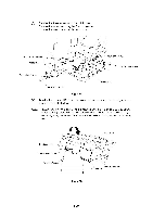
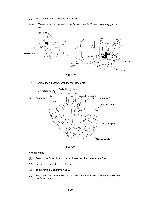
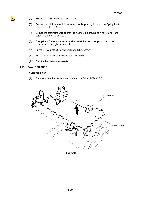
4.17 Power Supply PCB ASSY (1) Release all the harnesses from the grooves on the Main frame ASSY and lift the Shield plate upwards while carefully observing the Paper empty actuator. (2) Remove the four harnesses from the Power supply PCB ASSY. (3) Remove the five screws from the Power supply PCB. ti . , Groove Shield plate Shield plate DR ., "*.......f. .. 6, • Driver PCB ASSY Handset PS ASSY r , - J.---t 1 17 Power supply harness ASSY VH Power supply harness ASSY PH Fig. 4.47 (1) Position the Power supply PCB on the two bosses on the Shield plate. (2) Secure the Power supply PCB with five screws. (3) Securely connect the four harnesses to the connectors. (4) Put the harnesses in the grooves to make them tidy. (5) Stand the Paper empty actuator straight up and slowly position the Shield plate on the bosses on the Main frame ASSY while carefully checking so that the Paper empty actuator does not get caught under the Shield plate. III-32
-
 1
1 -
2
-
3
-
4
-
5
-
6
-
7
-
8
-
9
-
10
-
11
-
12
-
13
-
14
-
15
-
16
-
17
-
18
-
19
-
20
-
21
-
22
-
23
-
24
-
25
-
26
-
27
-
28
-
29
-
30
-
31
-
32
-
33
-
34
-
35
-
36
-
37
-
38
-
39
-
40
-
41
-
42
-
43
-
44
-
45
-
46
-
47
-
48
-
49
-
50
-
51
-
52
-
53
-
54
-
55
-
56
-
57
-
58
-
59
-
60
-
61
-
62
-
63
-
64
-
65
-
66
-
67
-
68
-
69
-
70
-
71
-
72
-
73
-
74
-
75
-
76
-
77
-
78
-
 79
79 -
 80
80 -
 81
81 -
 82
82 -
 83
83 -
 84
84 -
 85
85 -
 86
86 -
 87
87 -
 88
88 -
 89
89 -
90
-
91
-
92
-
93
-
94
-
95
-
96
-
97
-
98
-
99
-
100
-
101
-
102
-
103
-
104
-
105
-
106
-
107
-
108
-
109
-
110
-
111
-
112
-
113
-
114
-
115
-
116
-
117
-
118
-
119
-
120
-
121
-
122
-
123
-
124
-
125
-
126
-
127
-
128
-
129
-
130
-
131
-
132
-
133
-
134
-
135
-
136
-
137
-
138
-
139
-
140
-
141
-
142
-
143
-
144
-
145
-
146
-
147
-
148
-
149
-
150
-
151
-
152
-
153
-
154
-
155
-
156
-
157
-
158
-
159
-
160
-
161
-
162
-
163
-
164
-
165
-
166
-
167
-
168
 |
 |
