Brother International HS-5300 Service Manual - Page 73
spacer, frame, Screw
 |
View all Brother International HS-5300 manuals
Add to My Manuals
Save this manual to your list of manuals |
Page 73 highlights
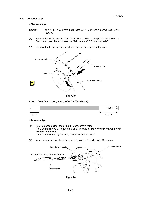
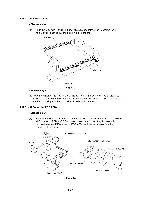
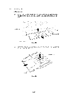
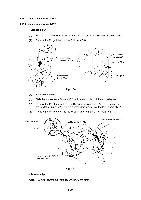
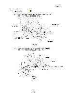
4.11.5 ROM PCB (Option) (1) Make sure that the power is turned off. (2) Release the clip at the top of the PCB spacer and remove the ROM PCB. (1) Reassemble the ROM PCB on the PCB spacer so that it is engaged with the connector. Note: Make sure that the ROM PCB is securely engaged with the connector. ROM PCB Main PCB PCB spacer Fig. 4.26 4.11.6 MIO PCB ASSY (Option) (1) Make sure that the power is turned OFF. (2) Remove the two screws and pull the MIO PCB ASSY toward you to remove it. Main frame ASSY z(7-' ___---------i% MIO PCB ASSY - 7 -- V /' -----------. err ,, c) 1 Screw, bind M3x6 Fig. 4.27 III-21
-
 1
1 -
2
-
3
-
4
-
5
-
6
-
7
-
8
-
9
-
10
-
11
-
12
-
13
-
14
-
15
-
16
-
17
-
18
-
19
-
20
-
21
-
22
-
23
-
24
-
25
-
26
-
27
-
28
-
29
-
30
-
31
-
32
-
33
-
34
-
35
-
36
-
37
-
38
-
39
-
40
-
41
-
42
-
43
-
44
-
45
-
46
-
47
-
48
-
49
-
50
-
51
-
52
-
53
-
54
-
55
-
56
-
57
-
58
-
59
-
60
-
61
-
62
-
63
-
64
-
65
-
66
-
67
-
 68
68 -
 69
69 -
 70
70 -
 71
71 -
 72
72 -
 73
73 -
 74
74 -
 75
75 -
 76
76 -
 77
77 -
 78
78 -
79
-
80
-
81
-
82
-
83
-
84
-
85
-
86
-
87
-
88
-
89
-
90
-
91
-
92
-
93
-
94
-
95
-
96
-
97
-
98
-
99
-
100
-
101
-
102
-
103
-
104
-
105
-
106
-
107
-
108
-
109
-
110
-
111
-
112
-
113
-
114
-
115
-
116
-
117
-
118
-
119
-
120
-
121
-
122
-
123
-
124
-
125
-
126
-
127
-
128
-
129
-
130
-
131
-
132
-
133
-
134
-
135
-
136
-
137
-
138
-
139
-
140
-
141
-
142
-
143
-
144
-
145
-
146
-
147
-
148
-
149
-
150
-
151
-
152
-
153
-
154
-
155
-
156
-
157
-
158
-
159
-
160
-
161
-
162
-
163
-
164
-
165
-
166
-
167
-
168
 |
 |

4.11.5
ROM
PCB
(Option)
<Disassembly>
(1)
Make
sure
that
the
power
is
turned
off.
(2)
Release
the
clip
at
the
top
of
the
PCB
spacer
and
remove
the
ROM
PCB.
<Reassembly>
(1)
Reassemble
the
ROM
PCB
on
the
PCB
spacer
so
that
it
is
engaged
with
the
connector.
Note:
Make
sure
that
the
ROM
PCB
is
securely
engaged
with
the
connector.
ROM
PCB
Main
PCB
PCB
spacer
Fig.
4.26
4.11.6
MIO
PCB
ASSY
(Option)
<Disassembly>
(1)
Make
sure
that
the
power
is
turned
OFF.
(2)
Remove
the
two
screws
and
pull
the
MIO
PCB
ASSY
toward
you
to
remove
it.
Main
frame
ASSY
)
-________
-
,
-
,
z
(-‘
___-----
----
i%
MIO
PCB
ASSY
-
7
--
V
Screw,
bind
M3x6
7
-----------.
c)
err
,,
/'
1
Fig.
4.27
III
-21