Brother International HS-5300 Service Manual - Page 72
<Reassembly>
 |
View all Brother International HS-5300 manuals
Add to My Manuals
Save this manual to your list of manuals |
Page 72 highlights
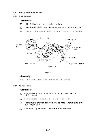
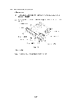
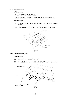
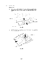
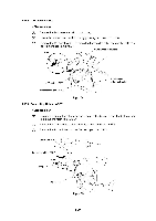
4.11.4 Rear Panel and PCB Angle Plate (1) Remove the two screws from the Rear panel and the two screws securing the parallel I/F connector. (2) Remove the two screws (one for each PCB angle bracket) from the bottom of the Main PCB. PCB angle bracket Rear panel . Main PCB Screw, bind M3X6 Screw, bind M3X6 Screws Screw, bind M3X6 ---469 Fig. 4.25 1 PCB angle bracket Screw, bind M3X6 Note: Tighten the PCB angle bracket as shown in fig. 4.25. III-20
-
 1
1 -
2
-
3
-
4
-
5
-
6
-
7
-
8
-
9
-
10
-
11
-
12
-
13
-
14
-
15
-
16
-
17
-
18
-
19
-
20
-
21
-
22
-
23
-
24
-
25
-
26
-
27
-
28
-
29
-
30
-
31
-
32
-
33
-
34
-
35
-
36
-
37
-
38
-
39
-
40
-
41
-
42
-
43
-
44
-
45
-
46
-
47
-
48
-
49
-
50
-
51
-
52
-
53
-
54
-
55
-
56
-
57
-
58
-
59
-
60
-
61
-
62
-
63
-
64
-
65
-
66
-
 67
67 -
 68
68 -
 69
69 -
 70
70 -
 71
71 -
 72
72 -
 73
73 -
 74
74 -
 75
75 -
 76
76 -
 77
77 -
78
-
79
-
80
-
81
-
82
-
83
-
84
-
85
-
86
-
87
-
88
-
89
-
90
-
91
-
92
-
93
-
94
-
95
-
96
-
97
-
98
-
99
-
100
-
101
-
102
-
103
-
104
-
105
-
106
-
107
-
108
-
109
-
110
-
111
-
112
-
113
-
114
-
115
-
116
-
117
-
118
-
119
-
120
-
121
-
122
-
123
-
124
-
125
-
126
-
127
-
128
-
129
-
130
-
131
-
132
-
133
-
134
-
135
-
136
-
137
-
138
-
139
-
140
-
141
-
142
-
143
-
144
-
145
-
146
-
147
-
148
-
149
-
150
-
151
-
152
-
153
-
154
-
155
-
156
-
157
-
158
-
159
-
160
-
161
-
162
-
163
-
164
-
165
-
166
-
167
-
168
 |
 |

4.11.4
Rear
Panel
and
PCB
Angle
Plate
<Disassembly>
(1)
Remove
the
two
screws
from
the
Rear
panel
and
the
two
screws
securing
the
parallel
I/F
connector.
(2)
Remove
the
two
screws
(one
for
each
PCB
angle
bracket)
from
the
bottom
of
the
Main
PCB.
PCB
angle
bracket
Rear
panel
Screw,
bind
M3X6
Screw,
bind
M3X6
Screws
Screw,
bind
M3X6
---469
Fig.
4.25
<Reassembly>
.
1
Note:
Tighten
the
PCB
angle
bracket
as
shown
in
fig.
4.25.
Main
PCB
PCB
angle
bracket
Screw,
bind
M3X6
III
-20