Brother International HS-5300 Service Manual - Page 85
Securely, connect, Power, supply, harness, Driver, After, replacing, adjustment, done.,
 |
View all Brother International HS-5300 manuals
Add to My Manuals
Save this manual to your list of manuals |
Page 85 highlights
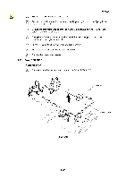
(6) Securely connect the Power supply harness ASSY VH and PH to the Driver PCB. Screw, bind M4X8 4 Shield plate Screw, pan M3X5 N Screw, bind M4X8 Power supply PCB ASSY Screw, bind M4X8 i Shield plate DR Fig. 4.48 Note: After replacing the Power supply PCB ASSY, adjustment must be done. See section 5.3 Electrical Adjustment and 5.4 Offset, TOF and LF Adjustment in this chapter. III-33
-
 1
1 -
2
-
3
-
4
-
5
-
6
-
7
-
8
-
9
-
10
-
11
-
12
-
13
-
14
-
15
-
16
-
17
-
18
-
19
-
20
-
21
-
22
-
23
-
24
-
25
-
26
-
27
-
28
-
29
-
30
-
31
-
32
-
33
-
34
-
35
-
36
-
37
-
38
-
39
-
40
-
41
-
42
-
43
-
44
-
45
-
46
-
47
-
48
-
49
-
50
-
51
-
52
-
53
-
54
-
55
-
56
-
57
-
58
-
59
-
60
-
61
-
62
-
63
-
64
-
65
-
66
-
67
-
68
-
69
-
70
-
71
-
72
-
73
-
74
-
75
-
76
-
77
-
78
-
79
-
 80
80 -
 81
81 -
 82
82 -
 83
83 -
 84
84 -
 85
85 -
 86
86 -
 87
87 -
 88
88 -
 89
89 -
 90
90 -
91
-
92
-
93
-
94
-
95
-
96
-
97
-
98
-
99
-
100
-
101
-
102
-
103
-
104
-
105
-
106
-
107
-
108
-
109
-
110
-
111
-
112
-
113
-
114
-
115
-
116
-
117
-
118
-
119
-
120
-
121
-
122
-
123
-
124
-
125
-
126
-
127
-
128
-
129
-
130
-
131
-
132
-
133
-
134
-
135
-
136
-
137
-
138
-
139
-
140
-
141
-
142
-
143
-
144
-
145
-
146
-
147
-
148
-
149
-
150
-
151
-
152
-
153
-
154
-
155
-
156
-
157
-
158
-
159
-
160
-
161
-
162
-
163
-
164
-
165
-
166
-
167
-
168
 |
 |

(6)
Securely
connect
the
Power
supply
harness
ASSY
VH
and
PH
to
the
Driver
PCB.
Screw,
bind
M4X8
Screw,
bind
M4X8
Power
supply
PCB
ASSY
Screw,
bind
M4X8
4
i
Shield
plate
Screw,
pan
M3X5
Shield
plate
DR
N
Fig.
4.48
Note:
After
replacing
the
Power
supply
PCB
ASSY,
adjustment
must
be
done.
See
section
5.3
Electrical
Adjustment
and
5.4
Offset,
TOF
and
LF
Adjustment
in
this
chapter.
III
-33