Brother International HS-5300 Service Manual - Page 80
Position
 |
View all Brother International HS-5300 manuals
Add to My Manuals
Save this manual to your list of manuals |
Page 80 highlights
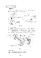
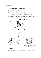
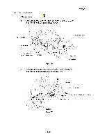
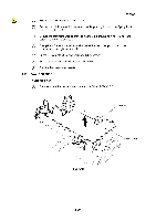
(5) Press the hook to release the Inlet holder. Note: The harness from the Inlet holder is still connected to the power supply at this stage. Base plate Hook Det Inlet holder Main frame ASSY Fig. 4.40 ( Inlet holder Base plate (6) Remove the 13 screws securing the Base plate. Taptite, bind B M4X10 Screw, bind M3.5X8 Taptite, bind B M4X10 Screw, bind M3.5X8 Taptite, bind B M4X10 Screw, bind M3.5X8 !;) N Base plate Main frame ASSY Fig. 4.41 (1) Position the Base plate on the two bosses on the Main frame ASSY. (2) Secure the Base plate with 13 screws. (3) Turn over the Main frame ASSY. (4) Press the Inlet holder and slide the hook of the Inlet holder until the hook secures the Base plate. III-28
-
 1
1 -
2
-
3
-
4
-
5
-
6
-
7
-
8
-
9
-
10
-
11
-
12
-
13
-
14
-
15
-
16
-
17
-
18
-
19
-
20
-
21
-
22
-
23
-
24
-
25
-
26
-
27
-
28
-
29
-
30
-
31
-
32
-
33
-
34
-
35
-
36
-
37
-
38
-
39
-
40
-
41
-
42
-
43
-
44
-
45
-
46
-
47
-
48
-
49
-
50
-
51
-
52
-
53
-
54
-
55
-
56
-
57
-
58
-
59
-
60
-
61
-
62
-
63
-
64
-
65
-
66
-
67
-
68
-
69
-
70
-
71
-
72
-
73
-
74
-
 75
75 -
 76
76 -
 77
77 -
 78
78 -
 79
79 -
 80
80 -
 81
81 -
 82
82 -
 83
83 -
 84
84 -
 85
85 -
86
-
87
-
88
-
89
-
90
-
91
-
92
-
93
-
94
-
95
-
96
-
97
-
98
-
99
-
100
-
101
-
102
-
103
-
104
-
105
-
106
-
107
-
108
-
109
-
110
-
111
-
112
-
113
-
114
-
115
-
116
-
117
-
118
-
119
-
120
-
121
-
122
-
123
-
124
-
125
-
126
-
127
-
128
-
129
-
130
-
131
-
132
-
133
-
134
-
135
-
136
-
137
-
138
-
139
-
140
-
141
-
142
-
143
-
144
-
145
-
146
-
147
-
148
-
149
-
150
-
151
-
152
-
153
-
154
-
155
-
156
-
157
-
158
-
159
-
160
-
161
-
162
-
163
-
164
-
165
-
166
-
167
-
168
 |
 |

(5)
Press
the
hook
to
release
the
Inlet
holder.
Note:
The
harness
from
the
Inlet
holder
is
still
connected
to
the
power
supply
at
this
stage.
Base
plate
Hook
Inlet
holder
Main
frame
ASSY
Fig.
4.40
(6)
Remove
the
13
screws
securing
the
Base
plate.
Screw,
bind
M3.5X8
Taptite,
bind
B
M4X10
Taptite,
bind
B
M4X10
;)
!
Fig.
4.41
Det
Screw,
bind
M3.5X8
Taptite,
bind
B
M4X10
N
(
Inlet
holder
Base
plate
Screw,
bind
M3.5X8
Base
plate
Main
frame
ASSY
<Reassembly>
(1)
Position
the
Base
plate
on
the
two
bosses
on
the
Main
frame
ASSY.
(2)
Secure
the
Base
plate
with
13
screws.
(3)
Turn
over
the
Main
frame
ASSY.
(4)
Press
the
Inlet
holder
and
slide
the
hook
of
the
Inlet
holder
until
the
hook
secures
the
Base
plate.
III
-28