HP LaserJet 5000 Service Manual
HP LaserJet 5000 Manual
 |
View all HP LaserJet 5000 manuals
Add to My Manuals
Save this manual to your list of manuals |
HP LaserJet 5000 manual content summary:
- HP LaserJet 5000 | Service Manual - Page 1
English HP LaserJet 5000, 5000 N and 5000 GN Printers Service Manual - HP LaserJet 5000 | Service Manual - Page 2
HP LaserJet 5000, 5000 N, and 5000 GN Printers Service Manual - HP LaserJet 5000 | Service Manual - Page 3
First Edition Warranty The information contained in this document is subject to change without notice. Hewlett-Packard makes no warranty of any kind with respect to this information. HEWLETT-PACKARD SPECIFICALLY DISCLAIMS THE IMPLIED WARRANTY OF MERCHANTABILITY AND FITNESS FOR A PARTICULAR PURPOSE - HP LaserJet 5000 | Service Manual - Page 4
Contents 1 Printer Description Overview 1-1 Printer Features 1-2 Identification 1-5 Model and Serial Numbers 1-5 Site Requirements 1-6 Space Requirements 1-7 Paper Specifications 1-11 Supported Types of Paper 1-14 Guidelines for Using Paper 1-15 Labels 1-18 Transparencies 1-18 Vellum 1- - HP LaserJet 5000 | Service Manual - Page 5
Serial MS-DOS Commands 3-38 Printer I/O Configuration 3-39 Parallel Menu 3-39 Serial Configuration 3-39 4 Printer Maintenance Overview 4-1 Cleaning the Printer and Accessories 4-2 Cleaning Spilled Toner 4-4 Preventative Maintenance 4-5 Reset Maintenance Count 4-5 Expected Life of Components - HP LaserJet 5000 | Service Manual - Page 6
/Output 5-14 CPU 5-14 Printer Memory 5-15 Random Access Memory (RAM 5-15 DIMM Slots 5-16 Memory Enhancement technology (MEt 5-16 Page Protect 5-16 PJL Overview 5-17 PML 5-17 Control Panel 5-17 Image Formation System 5-18 Toner Cartridge 5-20 Photosensitive Drum 5-21 Writing the Image - HP LaserJet 5000 | Service Manual - Page 7
6 Removing and Replacing Parts Overview 6-1 User Installable Accessories 6-2 Removal and Replacement Strategy 6-7 Required Tools 6-7 Removing Covers 6-10 Rear Door / Rear Output Bin 6-10 Top Cover 6-12 Control Panel Overlay and Control Panel 6-15 Toner Cartridge Door Assembly 6-17 Front - HP LaserJet 5000 | Service Manual - Page 8
6-79 Gear Assembly and PCA 6-81 Power Connector 6-82 Separation Roller 6-83 7 Troubleshooting Overview 7-1 Troubleshooting Process 7-2 Troubleshooting Process Flow 7-4 Troubleshooting the Printing System 7-6 Preliminary Operating Checks 7-6 Power On 7-7 Display 7-11 Event Log 7-12 Printer - HP LaserJet 5000 | Service Manual - Page 9
6 Contents EN - HP LaserJet 5000 | Service Manual - Page 10
1 Printer Description Overview This chapter discusses the following: q Printer Features q Identification q Site Requirements q Paper Specifications q Safety Information EN Overview 1-1 - HP LaserJet 5000 | Service Manual - Page 11
Typefaces 110 Scalable TrueTypeTM (80 built-in, 30 via FontSmart, all PS and PCL accessible) Memory Options HP LaserJet 5000: 4 MB RAM standard HP LaserJet 5000 N: 8 MB RAM standard HP LaserJet 5000 GN: 12 MB RAM standard Optional Memory: 2, 4, 8, 16 MB EDO DIMMs 32 MB SDRAM DIMM Expansion Slots - HP LaserJet 5000 | Service Manual - Page 12
mm) to 11 by 17 in (279 by 432) Paper Path Straight through from Tray 1 to rear output bin Or to top output bin Output Capacity 250-sheet top output bin 50-sheet rear output bin Paper Handling Options Duplexer, optional 250-sheet and 500-sheet universal tray assembly EN Printer Features 1-3 - HP LaserJet 5000 | Service Manual - Page 13
Table 1-2. Comparison of HP LaserJet 5000 Series Printers HP LaserJet HP LaserJet HP LaserJet 5000 5000 N 5000 GN Ethernet 10-T/ 10-2 optional standard standard Max. # 1.4 GB EIO Drive optional optional standard Duplexer optional optional optional Envelope feeder not available - HP LaserJet 5000 | Service Manual - Page 14
The model number and serial numbers are listed on identification labels located on the rear left side of the printer. The serial number is alphanumeric, such as USB0000146 for the HP LaserJet 5000 N printer. The serial number contains information about the Country of Origin, the Revision Level, the - HP LaserJet 5000 | Service Manual - Page 15
open flames, or ammonia fumes. If the printer is placed near a window, make sure the window has a curtain or blind to block any air ventilation systems. Table 1-3. Electrical Specifications Volts Frequency Amps 100-127 VAC±10% 50/60 Hz ±3Hz 11 amps 220-240 VAC±10% 50/60 Hz ±3Hz 5 amps - HP LaserJet 5000 | Service Manual - Page 16
18.7 in (47.5 cm) Space Requirements 55 in (139.8 cm) 24.6 in (62.5 cm) 11.9 in (30.3 cm) 18.5 in (47.0 cm) 10.6 in (27.0 cm) Figure 1-2 18.5 in (47.0 cm) 4.3 in (11.0 cm) Printer Dimensions, HP LaserJet 5000 18.6 in (47.3 cm) EN Site Requirements 1-7 - HP LaserJet 5000 | Service Manual - Page 17
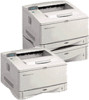
55 in (139.8 cm) 24.6 in (62.5 cm) 11.9 in (30.3 cm) 18.5 in (47.0 cm) 10.6 in (27.0 cm) Figure 1-3 6.1 in (15.5 cm) Printer Dimensions, HP LaserJet 5000 N/5000 GN 24.4 in (62.0 cm) 1-8 Printer Description EN - HP LaserJet 5000 | Service Manual - Page 18
.7 in (75.5 cm) Figure 1-4 Printer Dimensions, HP LaserJet 5000 with Accessories Printer Weight (without toner cartridge) q HP LaserJet 5000 printer: 50 lb (23 kg) q HP LaserJet 5000 N/5000 GN printers: 75 lb (34 kg) q HP LaserJet 5000 N/5000 GN printers with duplexer and optional 250-sheet feeder - HP LaserJet 5000 | Service Manual - Page 19
Requirements Table 1-4. Printer and Toner Cartridge Environmental Conditions Item Operating Storage Temperature 50-91° F (10-32° C) -4 to 140°F (-20 to 60°C) Relative Humidity 20-80% RH (with no condensation) 10% TO 95% RH Table 1-5. Acoustic Emissions (Per ISO 9296) Printer State Sound - HP LaserJet 5000 | Service Manual - Page 20
50 labels 10 envelopes 1. The printer supports a wide range of paper sizes. Check the printer software for supported sizes. To print custom-size paper see the User's Guide. 2. Capacity may vary depending on paper weight and thickness, and environmental conditions. EN Paper Specifications - HP LaserJet 5000 | Service Manual - Page 21
Capacity2 16 to 28 lb (60 to 105 g/m2) 250 sheets of 20 lb (75 g/m2) paper 50-100 transparencies 1. The printer supports a wide range of media sizes. Check the printer software for supported sizes. 2. Capacity may vary depending on media weight and thickness, and environmental conditions. 1-12 - HP LaserJet 5000 | Service Manual - Page 22
a wide range of media sizes. Check the printer software for supported sizes. 2. Capacity may vary depending on media weight and thickness, and environmental conditions. 3. To print rotated paper see the User's Guide. 4. To print custom-size paper see the User's Guide. EN Paper Specifications 1-13 - HP LaserJet 5000 | Service Manual - Page 23
Table 1-9. Paper Specifications, Optional Duplex Printing Accessory (Duplexer) Minimum Maximum Dimensions1 5.8 by 8.3 inches (148 by 210 mm) 11.7 by 17 inches (297 by 432 mm) Weight 16 to 28 lb (60 to 105 g/m2) 1. The printer supports a wide range of media sizes. Check the printer software for - HP LaserJet 5000 | Service Manual - Page 24
. Some paper causes print quality problems, jamming, or damage to the printer. For more specific information, see "Image Defects" on page 7-50. Table 1-10. Guidelines for Using Paper Symptom Problem with Paper Solution Poor print quality or toner adhesion. Problems with feeding. Too moist, too - HP LaserJet 5000 | Service Manual - Page 25
use letterhead paper that is printed with low-temperature inks, such as those used in some types of thermography. Do not use raised letterhead. The printer uses heat and pressure to fuse toner to the paper. Make sure that any colored paper or preprinted forms use inks that are compatible with the - HP LaserJet 5000 | Service Manual - Page 26
determine approximate equivalent points in weight specifications other than U.S. bond weight. 27 33 37 60 60 2 17 43 24 29 35 39 64 64 3 20 50 28 34 42 46 75 75 4 21 54 30 36 44 55 67 74 120 120 10 34 86 47 58 71 79 128 128 11 36 90 50 62 75 83 135 135 - HP LaserJet 5000 | Service Manual - Page 27
392° F (200° C), the printer's maximum temperature. For best results, close the rear output bin to print transparencies to the top output bin. To avoid damaging the printer, use only transparencies recommended for use in laser printers. If you have problems printing transparencies, use Tray - HP LaserJet 5000 | Service Manual - Page 28
) curl, and should not contain air. (Envelopes that trap air may cause problems.) q Condition: Make sure envelopes are not wrinkled, nicked, or otherwise damaged To prevent envelopes from wrinkling or jamming, open the rear output bin. Envelopes with Double-Side-Seams Double-side- Specifications 1-19 - HP LaserJet 5000 | Service Manual - Page 29
. For optimum printer performance, do not use paper heavier than 53 lb (199 g/m2) in Tray 1 or 28 lb (105 g/m2) in other trays. Paper that is too heavy might cause misfeeds, stacking problems, paper jams, poor toner fusing, poor print quality, or excessive mechanical wear. Note Printing on heavier - HP LaserJet 5000 | Service Manual - Page 30
damaged. Also, make sure the cards are not stuck together. Card Stock Guidelines q If cards curl or jam, try printing from Tray 1 and opening the rear output bin. q Set margins at least 0.08 in (2 mm) away from the edges of the paper. EN Paper - HP LaserJet 5000 | Service Manual - Page 31
other than those specified in this service manual may result in exposure to hazardous radiation. Canadian DOC Regulations Complies with Canadian EMC Class B requirements. > 1-22 Printer Description EN - HP LaserJet 5000 | Service Manual - Page 32
a Class B digital device, pursuant to Part 15 of the FCC rules. These limits installed and used in accordance with the instructions, it may cause harmful interference to radio radio/TV technician. Any changes or modifications to the printer that are not expressly approved by HP could void the user - HP LaserJet 5000 | Service Manual - Page 33
för osynlig laserstrålning, som överskrider gränsen för laserklass 1. HUOLTO HP LaserJet 5000, 5000 N, 5000 GN -kirjoittimen sisällä ei ole käyttäjän huollettavissa olevia kohteita. Laitteen kymättömälle lasersäteilylle laitteen ollessa toiminnassa. Älä katso säteeseen. 1-24 Printer Description EN - HP LaserJet 5000 | Service Manual - Page 34
by calling the U.S. HP FIRST (Fax Information Retrieval Support Technology) at (1) (800) 231-9300. Use Index number 7 for a listing of the Toner Cartridge/Drum Material/Chemical Safety Data Sheets. Non-U.S. customers should refer to the support section of the User's Guide for appropriate phone - HP LaserJet 5000 | Service Manual - Page 35
in the electrophotographic process and therefore generates no appreciable ozone gas (O3). Instead, this printer uses charging rollers in the toner cartridge and in the print engine. Energy Consumption This HP LaserJet printer design reduces: Energy usage drops to as little as 21 W while in low - HP LaserJet 5000 | Service Manual - Page 36
2 Service Approach Overview This chapter discusses the following: q Service Approach q Parts and Supplies q Warranty Statement EN Overview 2-1 - HP LaserJet 5000 | Service Manual - Page 37
troubleshooting procedures in Chapter 7. Once a faulty part is located, repair is generally accomplished by assembly level replacement of Field Replaceable Units (FRUs). Some mechanical assemblies may be repaired at the subassembly level. PCA component replacement is not supported by Hewlett-Packard - HP LaserJet 5000 | Service Manual - Page 38
in Chapter 8 of this manual. Replacement parts may be ordered from HP's Support Materials Organization (SMO) or Support Materials Europe (SME). Use only accessories specifically designed for this printer. Accessories can be ordered from an authorized service or support provider. See page 2-5 and - HP LaserJet 5000 | Service Manual - Page 39
Use Part Number HP LaserJet Printer Family Paper Specification Guide A guide to using paper and other print media with HP LaserJet printers. 5021-8909 PCL 5/PJL Technical Reference Documentation Package A guide to using printer 5021-0330 commands with HP LaserJet printers. HP LaserJet 5000 - HP LaserJet 5000 | Service Manual - Page 40
free technical support information 24 hours a day, 7 days a week. The ASAP system includes HP AUDIO-TIPS and HP FIRST, both explained below. The ASAP service 1-800-333-1917 (U.S.) requires a touchtone phone. To order additional printer drivers for software applications, call HP's Distribution Center - HP LaserJet 5000 | Service Manual - Page 41
-810061 Austria, 0660-8128 For English service outside the above countries, call (31) 20-681-5792. HP CompuServe Forum CompuServe™ members can download a variety of support materials including product data sheets, software application notes, and printer drivers for many popular software applications - HP LaserJet 5000 | Service Manual - Page 42
(NARC) The North American Response Center (NARC) is available to assist service technicians. The NARC can be reached at 1-800-544-9976. Other Areas Outside of North America and Europe, contact your local HP sales office for assistance in obtaining technical support. EN Parts and Supplies 2-7 - HP LaserJet 5000 | Service Manual - Page 43
-Packard warranty or maintenance contracts. q Hewlett-Packard has no control or process to ensure that a refilled Toner Cartridge functions at the high level of reliability of a new HP LaserJet Toner Cartridge. Hewlett-Packard also cannot predict what the long term reliability effect on the printer - HP LaserJet 5000 | Service Manual - Page 44
Warranty Statement This warranty gives specific legal rights. There may also be other rights which vary from area to area. Refer to the User's Guide for further warranty information, or see the warranty card included with the printer. EN Warranty Statement 2-9 - HP LaserJet 5000 | Service Manual - Page 45
2-10 Service Approach EN - HP LaserJet 5000 | Service Manual - Page 46
3 Printer Operation Overview This chapter discusses the following: q Using the Control Panel q Control Panel Menus q Service Mode q Testing the Printer q Resetting the Printer q System Configuration q Printer I/O Configuration EN Overview 3-1 - HP LaserJet 5000 | Service Manual - Page 47
Menu Item Cancel Job - Value + Select Figure 3-1 Control Panel Layout Control Panel Lights Table 3-1. Control Panel Lights Light Indication Ready The printer is ready to print. Data The printer is processing information. Attention Action is required. See the Control Panel display - HP LaserJet 5000 | Service Manual - Page 48
to resume printing after being offline. q Clears most printer messages and places the printer online. q Allows the printer to continue printing with an error message such as TRAY x LOAD [TYPE] [SIZE] or UNEXPECTED PAPER SIZE. q Confirms a manual feed request if Tray 1 is loaded and TRAY 1 MODE - HP LaserJet 5000 | Service Manual - Page 49
For example, a request from the software to print three copies instead of the Control Panel default value of one copy is a temporary setting. The printer continues to use the temporary setting until it receives another software request or until it is reset. Control Panel Default A value set at the - HP LaserJet 5000 | Service Manual - Page 50
trays or other accessories are installed in the printer, new menu items automatically appear. To change a Control Panel setting: 1 Press [ Settings in the printer driver and software application override Control Panel settings. (Software application settings override printer driver settings.) If you - HP LaserJet 5000 | Service Manual - Page 51
card is installed (HP LaserJet 5000 N/5000 GN printers), a JetDirect Configuration Page will print out as well. PRINT PCL FONT LIST The PCL font list shows all the PCL fonts currently available to the printer. PRINT PS FONT LIST The PS font list shows all the PS fonts currently available to - HP LaserJet 5000 | Service Manual - Page 52
duplex and manual feed) can be accessed from a software application, or from the printer driver (if the appropriate driver is installed). Printer driver the paper size currently loaded in Tray 1. TRAY 1 TYPE= PLAIN For supported paper types see page 1-14. This item appears only when TRAY 1 MODE - HP LaserJet 5000 | Service Manual - Page 53
from Tray 1, rather than automatically from a tray. When MANUAL FEED=ON and Tray 1 is empty, the printer goes offline when it receives a print job and displays MANUALLY FEED [PAPER SIZE]. DUPLEX=OFF OFF ON This item appears only when an optional duplexer is installed. Set the value to ON to - HP LaserJet 5000 | Service Manual - Page 54
problems printing on certain paper types.) NO: The fuser mode menu items are not accessible. YES: Additional items appear (see below). Note To see the default fuser NORMAL LOW HIGH VELLUM This item appears only when CONFIGURE FUSER MODE MENU=YES. Most paper types are set to NORMAL by default. ROUGH= - HP LaserJet 5000 | Service Manual - Page 55
When the resolution is changed, any downloaded resources (such as fonts or macros) will need to be downloaded again, unless they are stored on an optional hard disk or flash DIMM. Note It is best to change the resolution from the printer driver or software application. (Driver and software settings - HP LaserJet 5000 | Service Manual - Page 56
of toner on the printed page by up to 50%. Caution HP does not recommend fulltime use of EconoMode. (If EconoMode is used full-time, it is possible that the toner supply will outlast the mechanical parts in the Toner Cartridge.) Note It is best to turn EconoMode on or off from the printer driver or - HP LaserJet 5000 | Service Manual - Page 57
Note It is best to change the toner density from the printer driver or software application. (Driver and software settings override Control Panel settings.) Press [Select] to print a cleaning page (for cleaning excess toner from the paper path). In order for the cleaning page to work properly, print - HP LaserJet 5000 | Service Manual - Page 58
software application. (Driver and software settings override Control Panel settings.) PAPER= LETTER (110 V printers) and ENVELOPE= COM10 (110 V printers) For supported paper sizes see page 1-11. Set the default image size for paper and envelopes. (The item name will change from paper to envelope - HP LaserJet 5000 | Service Manual - Page 59
or software application. (Driver and software settings override Control Panel settings.) FORM=60 LINES (110 V printers) or 64 LINES (220 V printers) 5 to 128 Sets vertical spacing from 5 to 128 lines for default paper size. Press [-Value+] once to change the setting by increments of 1, or hold - HP LaserJet 5000 | Service Manual - Page 60
one of the three DIMM slots. The printer assigns a number to each font and lists them on the PCL Font List. The font number appears change the setting by increments of .01 for pitch, or hold down [-Value+] to scroll by increments of 1. Select any one of several available symbol sets from the printer - HP LaserJet 5000 | Service Manual - Page 61
TO LF= NO NO YES PRINT PS ERRORS=OFF OFF ON Explanation Select the version of Courier font to use: REGULAR: The internal Courier font available on the HP LaserJet 4 series printers. DARK: The internal Courier font available on the HP LaserJet III series printers. Both fonts are not available at - HP LaserJet 5000 | Service Manual - Page 62
AUTO AUTO PCL PS Select the default printer language (personality). Possible values are determined by which valid languages are installed in the printer. Normally you should not change the printer language (the default is AUTO). If you change it to a specific printer language, the printer will not - HP LaserJet 5000 | Service Manual - Page 63
so. Any time the amount of memory dedicated to a specific language is changed, all languages will lose all saved memory used for saving PCL resources. Printer default is the minimum amount of memory needed to perform resource saving for PCL. Press [-Value+] to change settings by increments of 10 - HP LaserJet 5000 | Service Manual - Page 64
This item appears only when RESOURCE SAVE=ON. Select the amount of memory used for saving PS resources. Printer default is the minimum amount of memory needed to perform resource saving for PS. Press [-Value+] to change settings by increments of 10 (up to 100 KB) or by increments of 100 (above 100 - HP LaserJet 5000 | Service Manual - Page 65
returning online. OFF: If an error occurs that prevents printing, the message will remain on the display and the printer will remain offline until [Go] is pressed. If the printer is on a network, you will probably want to turn AUTO CONTINUE to ON. TONER LOW=CONTINUE CONTINUE STOP Determine how - HP LaserJet 5000 | Service Manual - Page 66
of memory. This option uses engine video data for printing multiple original prints and should print all copies after the first at the printer's maximum speed. OFF: Disables the mopier functions. (The printer will not spool any jobs to the hard disk.) When the mopier mode is changed, any downloaded - HP LaserJet 5000 | Service Manual - Page 67
on the amount of installed memory.) Determine the size of the RAM disk. This item appears if RAM DISK=ON or AUTO. Press [-Value+] to change settings by increments of 100. Note This setting cannot be changed if RAM DISK=AUTO. Changing this value will cause the printer to reinitialize when it becomes - HP LaserJet 5000 | Service Manual - Page 68
be cleared and will not be displayed again until the next maintenance is due. The message should not be turned off unless the printer maintenance has been performed. If the required maintenance is not performed, the printer's performance will degrade. SMALL PAPER SPEED=NORMAL NORMAL SLOW Select - HP LaserJet 5000 | Service Manual - Page 69
change settings by increments of 1, or hold down [- Value +] to scroll by increments of 10. I/O BUFFER=AUTO AUTO ON OFF Allocate memory for I/O buffering. AUTO: The printer automatically reserves memory is changed, any downloaded resources (such as fonts or macros) will need to be downloaded again - HP LaserJet 5000 | Service Manual - Page 70
available for I/O buffering is determined by the amount of memory installed in the printer, the languages installed in the printer, and by other memory allocations that must be made. Press [-Value +] to change settings by increments of 10 (up to 100 KB) or by increments of 100 (above 100 KB). Select - HP LaserJet 5000 | Service Manual - Page 71
57600 115200 HIGH LOW Explanation This item appears only when SERIAL PACING=XON/XOFF. Select the method for generating XONs. ON: The printer sends an XON when the printer is online and when sufficient buffer space is available. If the host does not receive data within approximately one second, the - HP LaserJet 5000 | Service Manual - Page 72
Menu. These and other parameters can also be configured through HP JetAdmin. Table 3-10. EIO Menu Item Values Explanation CFG NETWORK=NO NO NO stack OFF is enabled (on) or disabled (off). TCP/IP=ON ON Select whether the TCP/IP protocol stack is OFF enabled (on) or disabled (off). ETALK - HP LaserJet 5000 | Service Manual - Page 73
to be automatically loaded from a bootp or DHCP server when the printer is turned on. If you specify BOOTP=NO, you can manually set selected TCP/IP parameters from the Control Panel. You can manually set each byte of the IP address (IP), Subnet Mask (SM), Syslog Server (LG), and Default Gateway (GW - HP LaserJet 5000 | Service Manual - Page 74
and computer has been interrupted. q You are using both the serial and parallel I/O ports, and one of the ports is having problems. The items in the Resets Menu will clear all memory in the printer, while [Cancel Job] clears only the current job. Table 3-11. Resets Menu Item Explanation RESET - HP LaserJet 5000 | Service Manual - Page 75
only). q Clear the event log. q Set the interval at which the PERFORM PRINTER MAINTENANCE message appears on the control panel. To enter Service Mode: 1 Hold down [Select] and [Cancel Job] while turning on the printer. (If the control panel reads INITIALIZING, the keys were released too soon - HP LaserJet 5000 | Service Manual - Page 76
3-2 Note Service Menu Setting the Page Count, Maintenance Count, and Serial Number The page count and serial numbers are stored in Non-Volatile Memory. If Page to verify the current page count and serial number of the printer, if possible. Use the information on the Configuration Page to reset the - HP LaserJet 5000 | Service Manual - Page 77
by installing a new Formatter, the page count must be reset so that it represents the age of the printer's engine rather than the age of the Formatter. The page count value is changed using a different method than is used for other control panel values. Instead of increasing the entire value by - HP LaserJet 5000 | Service Manual - Page 78
. Advance to the first item in the SERVICE MENU. Advance the cursor one digit to the right. Advance the cursor one digit to the right. Increase the value of the third digit by one. Enter the change to the third digit and advance the cursor one digit to the right. Advance the - HP LaserJet 5000 | Service Manual - Page 79
Mode Menu sets the page count interval at which the next service is due for the printer. This is set initially at the factory to 150,000 pages. (For example, the message displays at 150,000 pages. If the Printer Maintenance Kit is installed at 150,114 pages, the message displays 150,000 pages - HP LaserJet 5000 | Service Manual - Page 80
interface, and then prints a test page. You can review the Configuration Page printout to verify proper installation of such options as paper trays or printer languages. For more information, see page 7-45. Engine Test The engine test print can be used to verify that the print engine is functioning - HP LaserJet 5000 | Service Manual - Page 81
printer memory and sets all the defaults back to the factory settings. Performing a Cold Reset resets the JetDirect configuration. To avoid making changes Press [Go] to return the printer online. READY appears on the display. Clearing NVRAM This procedure will clean up the NVRAM by removing old - HP LaserJet 5000 | Service Manual - Page 82
Most IBM and AT compatible computers default to a parallel printer port. To ensure that information is sent to your parallel printer port, type the following MS-DOS command at your MS PATH command in the AUTOEXEC.BAT file. After changing the AUTOEXEC.BAT file, reboot the computer to initiate the - HP LaserJet 5000 | Service Manual - Page 83
), the program file must be contained either in the root directory or in a directory specified in a preceding PATH command in the AUTOEXEC.BAT file. After changing the AUTOEXEC.BAT file, reboot the computer to initiate the changes. 3-38 Printer Operation EN - HP LaserJet 5000 | Service Manual - Page 84
HP LaserJet Explorer, the Windows® Printing System, and other software applications and drivers. Serial Configuration Use RS-232C serial configuration when the printer is located 11 to 50 set on both the printer and the computer. Protocol on the printer is set by changing the control panel settings. - HP LaserJet 5000 | Service Manual - Page 85
another signal to the computer to send more data. Pacing is set through the control panel's I/O Menu. Two types of handshaking are supported by the printer: q Select DTR/DSR through the I/O Menu's PACING item if the computer requires hardware flow control (most personal computers do). Through the - HP LaserJet 5000 | Service Manual - Page 86
4 Printer Maintenance Overview This chapter discusses the following: q Cleaning the Printer and Accessories q Preventative Maintenance EN Overview 4-1 - HP LaserJet 5000 | Service Manual - Page 87
clean the printer and the paper handling accessories: q Every time you change the Toner Cartridge (run a cleaning page). q After printing approximately 15,000 pages. q Whenever print quality problems occur. Clean the outside surfaces with a lightly water-dampened cloth. Clean the inside parts - HP LaserJet 5000 | Service Manual - Page 88
Table 4-1. Cleaning the Printer Component Cleaning Method / Notes Outside Covers Use a water-dampened cloth. Do not use solvents or ammoniabased cleaners. Inside General With a dry lint-free cloth, wipe any dust, spilled toner, and paper particles from the paper path area, the registration - HP LaserJet 5000 | Service Manual - Page 89
develop leaks. Also, after a paper jam has occurred, there may be some toner remaining on the rollers and guides inside the printer. The pages that print immediately after the jam may pick up this toner. Clean spilled toner with a cloth dampened with cold water. Do not touch the Transfer Roller with - HP LaserJet 5000 | Service Manual - Page 90
Preventative Maintenance The preventative maintenance cycle for this printer, conducted by service personnel, is every 150,000 pages. To order the maintenance kit see page 8-4. The kit contains one Fuser, one Transfer Roller, one Tray 1 Pickup Roller, one Tray 1 Separation Pad, two 250-sheet Tray - HP LaserJet 5000 | Service Manual - Page 91
Table 4-2. Life of Components (continued) Part name Part No. 6 Transfer Charging RG5-3579-000CN Roller 7 Exhaust Fan RH7-1354-000CN Quantity Expected Life 1 150,000 pages 1 25,000 hours 4-6 Printer Maintenance EN - HP LaserJet 5000 | Service Manual - Page 92
5 Functional Information Overview This chapter discusses the following: q Power Supply Subsystem q DC Controller Subsystem q Formatter PCA q Control Panel q Interface PCA q Image Formation System q Paper Feed System q Basic Sequence of Operation EN Overview 5-1 - HP LaserJet 5000 | Service Manual - Page 93
Printer Subsystems This chapter presents a generalized functional overview of the printer and the printing processes. Figure 5-1 Paper Feed Subsystem 5-2 Functional Information EN - HP LaserJet 5000 | Service Manual - Page 94
System AC/DC Power Distribution The AC line voltage for the printer is applied through the main switch (SW101) and supplied to to ICs on the DC controller PCA and the BD PCA. +5 VDC is supplied to the laser driver PCA and sensors. +24 VDC is supplied to the high-voltage power supply PCA to drive the - HP LaserJet 5000 | Service Manual - Page 95
Low Voltage Power Supply Circuit If a short circuit or other problems on the load side cause an excessive current flow from DC voltage, it is necessary to turn the power off, correct the problem in the faulty load, then turn the printer on again. The circuit has two fuses which break and cut off the - HP LaserJet 5000 | Service Manual - Page 96
monitors an abnormal rise of the fusing roller temperature. If an error occurs, this circuit outputs a signal to turn the relay ( 1 goes "L," Q4 turns off, then the relay (RL1) turns off. The printer has the following three protection functions to prevent wrong activation of the fusing roller heater - HP LaserJet 5000 | Service Manual - Page 97
High Voltage Power Distribution Figure 5-3 High Voltage Power Supply Circuit In response to the instructions from the microprocessor (CPU: IC301) on the DC controller, this circuit applies the superimposed voltage of DC voltage and AC voltage to the primary charging - HP LaserJet 5000 | Service Manual - Page 98
inside the cartridge, and outputs the toner detection signal. The CPU detects the remaining toner level and the presence of the The operation sequences of this printer are controlled by the CPU of this circuit. When the printer power switch is turned on and the printer enters the standby mode, - HP LaserJet 5000 | Service Manual - Page 99
Figure 5-4 DC Controller PCA Laser and Scanner Drive Based on information received from the Formatter, the DC Controller Board sends signals to the Laser/Scanner Assembly to modulate the laser diode on and off and to drive the Laser/Scanner motor. See "Image Formation System" on page 5-18 for more - HP LaserJet 5000 | Service Manual - Page 100
Paper Motion Monitoring and Control The DC Controller Board controls paper motion by continuously monitoring the various paper sensors, and coordinating paper movement with the other print processes. For more information, see "Paper Feed System" on page 5-29. Solenoids, Sensors, Clutches, and - HP LaserJet 5000 | Service Manual - Page 101
See "Timing Diagram" on page 5-47 for specific timing details for the printer motors. The Main Motor, MT1, is controlled -on), the Print period, the Last Rotation period, or whenever the printer's Top Cover is opened and closed. Figure 5-5 Main Motor Control The Main Motor is a DC brushless motor - HP LaserJet 5000 | Service Manual - Page 102
. The fan motor is a two-phase, four-pole DC brushless motor containing a hall element and forms a unit along with the motor drive circuit. When the printer turns on, the CPU (IC301) on the DC controller PCA makes pin 99 (/HALFFAN) "H" and runs the fan motor half a turn. The CPU controls the - HP LaserJet 5000 | Service Manual - Page 103
and instructions memory DIMMs, and the Hard Disk accessory. PowerSave This feature (accessed from the Configuration Menu) conserves power by shutting down the Fuser and exhaust fans after the printer has been idle for an adjustable period of time. The printer retains all printer settings, downloaded - HP LaserJet 5000 | Service Manual - Page 104
and then closed. q A paper tray is opened and then closed. q The Engine Test button is pressed. Printer error messages override the PowerSave message. The printer will enter or printer drivers override the Control Panel settings. EconoMode The EconoMode setting uses up to 50% less toner than - HP LaserJet 5000 | Service Manual - Page 105
and the host, allowing the user to change printer settings and monitor printer status from the host computer. The user may configure the HIGH SPEED item in the Control Panel menu. The default setting, YES, allows the I/O to run at the higher speeds supported by most newer computers. When set to - HP LaserJet 5000 | Service Manual - Page 106
] is pressed. If an error occurs that prevents printing and AUTO CONTINUE=ON is set, the printer goes offline for 10 seconds before it returns online Protect" on page 5-21). RAM memory capacities for each printer are shown in "Printer Features" on page 1-2. Memory capacity can be increased by adding - HP LaserJet 5000 | Service Manual - Page 107
and forms in the printer. Memory Enhancement technology (MEt) The Hewlett-Packard Memory Enhancement technology (MEt) effectively doubles the standard memory through a variety of font and data compression methods. MEt is only available in PCL mode; it is not functional when printing in PS mode. Page - HP LaserJet 5000 | Service Manual - Page 108
PJL) is an integral part of configuration, in addition to the standard Printer Command Language (PCL). With standard cabling, PJL allows the printer to perform functions such as: q Two-way communication with the host computer through a Bidirectional Parallel connection. The printer can tell the host - HP LaserJet 5000 | Service Manual - Page 109
on the photosensitive drum is changed to a visual image by the toner on the developing cylinder, then transferred to the paper by the transfer charging roller. The residual toner on the photosensitive drum surface is scraped down with the cleaning blade. The potential on the drum is uniformed by - HP LaserJet 5000 | Service Manual - Page 110
Figure 5-6 Image Formation System After the image has been transferred to the paper, it is then fused onto the paper by heat and pressure at the Fuser. EN Image Formation System 5-19 - HP LaserJet 5000 | Service Manual - Page 111
the photosensitive drum, primary charging roller, developing station, toner cavity, and cleaning station. Including these components that wear, degrade, or are consumed in the replaceable Toner Cartridge eliminates the need for a service call when replacement is required. The printer also has - HP LaserJet 5000 | Service Manual - Page 112
similar to a photo-resistor. It becomes electrically conductive when exposed to light. (The negative charges deposited on the drum are conducted to the ground potential of the drum base.) Areas not exposed to light remain non-conductive and maintain their negative charge. The aluminum base of the - HP LaserJet 5000 | Service Manual - Page 113
print image will be clear and distinct. Figure 5-9 Cleaning the Drum The residual toner on the drum surface is scraped away with the cleaning blade to clean the drum surface in preparation for the next print. The removed toner is collected into the cleaner container. 5-22 Functional Information - HP LaserJet 5000 | Service Manual - Page 114
the Drum After the drum is cleaned, it must be conditioned. This process consists of applying a uniform negative charge on the surface of the drum erase any residual charges and maintain a constant drum surface to create a uniform negative potential on the drum surface. The amount of DC voltage is - HP LaserJet 5000 | Service Manual - Page 115
rear of the Toner Cartridge, and onto the photosensitive drum. The beam sweeps the drum Driver Cylindrical Lens Photosensitive Drum the printer achieves its 1200x1200 dpi resolution. After the writing process, the drum problems with the laser diode or scanner motor. 5-24 Functional Information EN - HP LaserJet 5000 | Service Manual - Page 116
the Control Panel Menu adjusts the DC bias of the developing cylinder by changing the force of attraction between the toner and drum. A change in the DC bias causes either more or less toner to be attracted to the drum, which in turn either increases or decreases the print density. Both the primary - HP LaserJet 5000 | Service Manual - Page 117
roller causes the negatively charged toner on the drum surface to be attracted to the page. The small diameter of the drum, combined with the stiffness of drum. The static eliminator teeth weaken the attractive forces between the negatively charged drum surface. After separation, the drum is cleaned - HP LaserJet 5000 | Service Manual - Page 118
a heated fusing roller and a soft pressure roller. This melts the toner and presses it into the paper. The fusing roller contains a ceramic a relay opens, interrupting power to the Fusing Heater, causing a Fuser error message (50.X FUSER ERROR). If the fusing system exceeds 464° F (240° C), the - HP LaserJet 5000 | Service Manual - Page 119
the user or service technician the ability to adjust the fusing temperature based on the media being used in the printer. The default mode used, then High Fuser Mode is beneficial. If transparencies or light media are being used, then Low Fuser Mode might be appropriate. CONFIGURE FUSER MODE is in - HP LaserJet 5000 | Service Manual - Page 120
of the paper in Tray 2 and the presence of Tray 2 installed in the printer are detected by four switches (SW403, SW404, SW405, and SW406) on the terminal and the feed roller start rotating to feed a sheet of paper into the printer. When the paper is fed from Tray 1, the Tray 1 pickup solenoid (SL404 - HP LaserJet 5000 | Service Manual - Page 121
The paper then passes through the transfer unit, separation unit, fuser, and deliver unit and is output onto the rear output bin or the top output bin. There are three photointerrupters Diagrams" starting on page 7-79 for locations of switches, sensors, and clutches. 5-30 Functional Information EN - HP LaserJet 5000 | Service Manual - Page 122
sheets are removed with the separation pad, and only one sheet is fed into the printer as the Tray 1 feed roller rotates. The paper passes through the registration roller paper transfer unit, the separation unit, the fuser, and the delivery unit, and outputs it onto the tray. EN Paper Feed System - HP LaserJet 5000 | Service Manual - Page 123
Figure 5-17 Tray 1 Pickup 5-32 Functional Information EN - HP LaserJet 5000 | Service Manual - Page 124
up one sheet of paper from the tray. The paper is fed into the printer as the feed roller rotates. The paper passes through the registration roller paper sensor and feeds the paper through the transfer unit, separation unit, fuser, and delivery unit and outputs it onto the tray. Figure 5-18 Tray - HP LaserJet 5000 | Service Manual - Page 125
Figure 5-19 Paper Skew Loop-forming 5-34 Functional Information EN - HP LaserJet 5000 | Service Manual - Page 126
by the paper handling PCA. The paper handling PCA has the 8-bit microcomputer, and controls the serial communications between the operation sequence control of paper handling PCA sends the status of the paper feeder back to the printer at the same time. (Refer to page 7-74 for the wiring diagrams.) Figure - HP LaserJet 5000 | Service Manual - Page 127
Figure 5-21 500-sheet Paper Feeder 5-36 Functional Information EN - HP LaserJet 5000 | Service Manual - Page 128
whether the paper has been correctly fed, the following paper sensors are installed: q Registration roller paper sensor (PS403) q Top of page sensor (PS402) q Fuser paper delivery sensor (PS1306) If the paper does not reach or pass through any of the sensors within the specified period of time, the - HP LaserJet 5000 | Service Manual - Page 129
This function is to reverse the one side printed paper from the printer and refeed it into the printer. The Duplexer operation sequence is controlled by the duplex driver PCA. The duplex driver PCA has the 8-bit microcomputer, which controls the serial communications between the operation sequence - HP LaserJet 5000 | Service Manual - Page 130
Figure 5-22 Paper Feed for the Duplexer EN Paper Feed System 5-39 - HP LaserJet 5000 | Service Manual - Page 131
Reversing System The duplexing driver PCA receives the duplex admission command from the printer first. It turns on the Duplexer deflector drive solenoid (SL1701), and the Duplexer deflector in the printer then starts to send the paper into the Duplexer. Within a specified period of time after - HP LaserJet 5000 | Service Manual - Page 132
Figure 5-24 Duplexing Unit EN Paper Feed System 5-41 - HP LaserJet 5000 | Service Manual - Page 133
The printer sends the command to the duplexing driver PCA by receiving the uncurling command sent from the formatter PCA. The duplexing driver PCA out about 30 mm from the duplexing unit along the uncurling guide and pauses for about one second. Then, the duplexing driver PCA starts to rotate the - HP LaserJet 5000 | Service Manual - Page 134
(CCW), and the reversing rollers 1, 2, and 3 rotate in reverse. In this way, the paper comes out from the duplexing unit about 125 mm and pauses. Then, the duplexing driver PCA rotates PM1701 clockwise (CW). Accordingly, the reversing rollers 1, 2, and 3 are rotated in reverse, and the paper refeeds - HP LaserJet 5000 | Service Manual - Page 135
Figure 5-26 Dance Mode Paper Jam in the Duplexer The following sensors are located to detect the presence of paper and to determine whether the paper is correctly fed. q reversing unit paper sensor (PS1701) q - HP LaserJet 5000 | Service Manual - Page 136
Purpose Remark WAIT From power on until the Main Motor completes the initial drive. Clears the drum surface potential and cleans the transfer charging roller. During this period, the printer detects the toner level and the presence of the cartridge. STBY (standby) From the end of the WAIT - HP LaserJet 5000 | Service Manual - Page 137
Remark LSTR (last rotations) After the primary DC voltage Delivers the final page turns off until the Main Motor and cleans the transfer stops. charging roller. As soon as the /PRNT signal is input from the Formatter PCA, the printer enters the INTR period. 5-46 Functional Information EN - HP LaserJet 5000 | Service Manual - Page 138
Figure 5-27 Timing Diagram EN Basic Sequence of Operation 5-47 - HP LaserJet 5000 | Service Manual - Page 139
5-48 Functional Information EN - HP LaserJet 5000 | Service Manual - Page 140
6 Removing and Replacing Parts Overview This chapter discusses the following: q User Installable Accessories q Removal and Replacement Strategy q Removing Covers q Removing Assemblies EN Overview 6-1 - HP LaserJet 5000 | Service Manual - Page 141
, print a configuration page to find out how much memory is installed in the printer before adding more memory. 1 Turn the printer off. Unplug the power cord and disconnect any cables. (If an optional duplexer is installed, you will need to remove the rear section and the cable tray first.) 2 Loosen - HP LaserJet 5000 | Service Manual - Page 142
the cable tray and the rear section of the duplexer. Reattach any interface cables and the power cord. Turn the printer on and test the DIMM. Note Single in-line memory modules (SIMMs) used on previous HP LaserJet printers are not compatible with the printer. EN User Installable Accessories 6-3 - HP LaserJet 5000 | Service Manual - Page 143
duplexer is installed: 1 Slide the rear section of the duplexer away from the printer. 2 Remove the rear section of the duplexer by lifting and rotating the rear Reverse these steps to install the cable tray and the rear section of the duplexer. Make sure the cable tray is properly installed and the - HP LaserJet 5000 | Service Manual - Page 144
amount of memory has not increased, the DIMM might not be installed correctly (repeat the installation procedure), or the DIMM might be defective (try a new DIMM). 4 See Chapter 7, Troubleshooting, for additional information. Installing EIO Cards / Mass Storage Turn off the printer before installing - HP LaserJet 5000 | Service Manual - Page 145
Figure 6-1 Installing EIO Cards or Mass Storage Devices 6-6 Removing and Replacing Parts EN - HP LaserJet 5000 | Service Manual - Page 146
of the screw-hole or replacement of the affected assembly is required. CAUTION The printer contains parts that are electrostatic discharge (ESD) sensitive. Always service printers at an ESD-protected workstation. Required Tools q Phillips #2 magnetized screwdriver (6-inch shaft) q Small, flat - HP LaserJet 5000 | Service Manual - Page 147
6-2 Phillips vs. Posidriv Screwdrivers Table 6-1. Screws Used in the Printer Drawing and Description Purpose Threaded Phillips with captive star washer Used to . Black Self-tapping Phillips screw 6-8 Removing and Replacing Parts Used to fasten metal or plastic to plastic mainframes. EN - HP LaserJet 5000 | Service Manual - Page 148
Table 6-1. Screws Used in the Printer (continued) Drawing and Description Purpose Threaded Phillips screw with lock and flat washer Used to fasten metal or plastic to threaded plastic or metal. Spring - HP LaserJet 5000 | Service Manual - Page 149
Removing Covers Rear Door / Rear Output Bin 1 Face the rear of the printer. Press the two locking tabs toward the center of the printer, releasing the Rear Door. Figure 6-3 Rear Door/Rear Output Bin . Item A Explanation Locking Tabs 6-10 Removing and Replacing Parts EN - HP LaserJet 5000 | Service Manual - Page 150
, and your thumb on top of the tab. Squeeze and lift up from the bottom, while pulling out (Figure 6-4). Figure 6-4 Hint Support Strap 3 Slide the door to the left, and then remove it from the printer. For reassembly, insert the pin on the left side of the cover first. EN Removing Covers 6-11 - HP LaserJet 5000 | Service Manual - Page 151
printer, open the Top Cover and remove the Toner Cartridge. To prevent damage to the toner cartridge, do not expose it to light for more than a few minutes. Figure 6-5 Toner Cartridge Engagement Arm 1 Release the Toner , and slide the shaft through the ring. 6-12 Removing and Replacing Parts EN - HP LaserJet 5000 | Service Manual - Page 152
is critical that step 1 be performed before you attempt to remove the Top Cover. If you damage the Arm, the printer will not operate. A Top screws B Toner Cartridge Drive Arm C Rear screws 2 Remove the two self-tapping screws on the top of the chassis. 3 Remove the two self-tapping screws on - HP LaserJet 5000 | Service Manual - Page 153
4 The cable connecting the Control Panel to the printer chassis is on the left side of the Top cover. Figure 6-6 Control Panel Cable 5 Disconnect the Control Panel cable from the printer chassis by grasping the wires and gently pulling the connector straight up. 6 Remove the Top Cover. - HP LaserJet 5000 | Service Manual - Page 154
Control Panel Overlay and Control Panel 1 Remove the Top Cover (page 6-12). 2 The Control Panel Overlay is held in place on the Top Cover by two tabs on each side. Slide a small flat-blade screwdriver along the outside edge of the Control Panel Overlay, to disengage the two tabs on the outside of - HP LaserJet 5000 | Service Manual - Page 155
Figure 6-8 Back Side of Top Cover Item A B Explanation Direction to slide control panel out Screw 6-16 Removing and Replacing Parts EN - HP LaserJet 5000 | Service Manual - Page 156
6-15). (The Control Panel must be removed before you can separate the Toner Cartridge Door from the Top Cover.) 3 Disengage the pins (A) by pressing outward, as shown below. Figure 6-9 Toner Cartridge Door Assembly (Under Side of Top Cover Door) Item A Explanation Pins EN Removing Covers 6-17 - HP LaserJet 5000 | Service Manual - Page 157
Open the Front Cover door. 2 Disengage the Tray 1 Guide pins from inside the Front Cover by pushing the Guides (C) outward. The Cover and Tray 1 will be separated. Press Tray 1 Guide against the printer. Figure 6-10 Front Cover Item A B C Explanation Front Cover Tray 1 Guide Guides 3 Release the - HP LaserJet 5000 | Service Manual - Page 158
Figure 6-11 Tray 1 4 Release the Tray 1 Guide by allowing the guide to slide off the keyed pins at its lowest position (Figure 6-11). EN Removing Covers 6-19 - HP LaserJet 5000 | Service Manual - Page 159
-tighten. If a self-tapping screw-hole becomes stripped, repair of the screw-hole or replacement of the affected assembly is required. 6-20 Removing and Replacing Parts EN - HP LaserJet 5000 | Service Manual - Page 160
Face Down Assembly 1 Remove the Top Cover (page 6-12). 2 Face the back of the printer. 3 Squeeze the locking tabs inward, one side at a time, to release the Face Down Assembly. See Figure 6-13 4 Lift slightly and then remove the Assembly - HP LaserJet 5000 | Service Manual - Page 161
Figure 6-14 Face Down Assembly Item A Explanation Locator Pins 6-22 Removing and Replacing Parts EN - HP LaserJet 5000 | Service Manual - Page 162
Left and Right Side Covers The removal procedure is the same for both the left and the right side covers. See Figure 6-15. 1 Remove the Top Cover (page 6-12). 2 Locate the tab in the top middle of the cover. Release the tab by pushing down on it. 3 Grab the side cover at the top by the front edge. - HP LaserJet 5000 | Service Manual - Page 163
. See Figure 6-16. 2 The Tray 1 Inner Cover is a plastic tray located at the top front of the printer. Remove the two self-tapping screws, (A) in Figure 6-17, holding the Cover to the front of the chassis. replacement of the affected assembly is required. 6-24 Removing and Replacing Parts EN - HP LaserJet 5000 | Service Manual - Page 164
Figure 6-17 Tray 1 Inner Cover (front of printer) Item A Explanation Screws Hint An extension of the Paper Sensor Flag fits into a slot in the Tray 1 Lift Plate (page 6-56). Orient the flag so - HP LaserJet 5000 | Service Manual - Page 165
Right and Left Corner Covers These covers are each secured by one self-tapping screw. Remove the screw, and lift off the cover. Figure 6-18 Right and Left Corner Covers Item A Explanation Corner Cover Screws 6-26 Removing and Replacing Parts EN - HP LaserJet 5000 | Service Manual - Page 166
are shown in Figure 6-19. All references to the right and left are assumed to be relative to the front of the printer, unless otherwise specified. Figure 6-19 Internal Assemblies Item A B C D E F Explanation Upper Delivery Assembly Laser Scanner Main Gear Assembly Paper Handling PCA Tray 1 Paper - HP LaserJet 5000 | Service Manual - Page 167
it up in a clean sheet of paper to protect it after removal. 1 Face the front of the printer, and lift the small Guide. Be careful not to touch the Transfer Roller with your fingers. Figure 6-20 Transfer Guide Removal Item A B Explanation Screws Transfer Guide 6-28 Removing and Replacing Parts - HP LaserJet 5000 | Service Manual - Page 168
Roller is held on the right side by a hinged clip. 2 Free the Transfer Roller from the hinged clip by lifting straight up using the blue cleaning brush located inside of the top cover (Figure 6-21). 3 Free the left side of the Transfer Roller by lifting straight up. Remove the Transfer Roller - HP LaserJet 5000 | Service Manual - Page 169
Note Fuser 1 Remove the Rear Door and Rear output bin (page 6-10). 2 Facing the back of the printer, remove the two machine screws holding the Fuser in the chassis. See Figure 6-22. 3 Using a small, flat bladed screw driver, lift at "D" to disengage the Fuser Assembly detents. Grasp the green - HP LaserJet 5000 | Service Manual - Page 170
Paper Handling PCA 1 Remove the Top Cover (page 6-12) and Left Side Cover (page 6-23). 2 Facing the left side of the printer, disconnect the ribbon cable from the PCA. 3 Remove two self-tapping screws and two machine screws from the PCA. 4 Rotate the PCA outward, and disconnect - HP LaserJet 5000 | Service Manual - Page 171
2. Check that the top margin is 2.0 mm. If the value is incorrect, repeat steps 1 through 4. Figure 6-24 Adjusting the Top Margin 6-32 Removing and Replacing Parts EN - HP LaserJet 5000 | Service Manual - Page 172
Figure 6-25 Location of VR401 EN Removing Assemblies 6-33 - HP LaserJet 5000 | Service Manual - Page 173
Assembly to the chassis. Figure 6-26 Main Gear Assembly, Left Side Item A B C Explanation Main Motor Cables Self-tapping Screws Grounding Screw 6-34 Removing and Replacing Parts EN - HP LaserJet 5000 | Service Manual - Page 174
(Figure 6-27), and then lower it to release the Locating Tab (A) and remove the Main Gear Assembly. Use caution when removing the assembly. The Toner Cartridge Engagement Arm may break if not handled carefully. Remember to reconnect the cable at the top of the Main Gear Assembly after reinstalling - HP LaserJet 5000 | Service Manual - Page 175
the screws. 3 Release the small spring (B) on the gear. 4 Remove the Gear Assembly from the chassis. Figure 6-28 Pickup Gear Assembly (left side view of printer - Main Gear Assembly has not been removed) 6-36 Removing and Replacing - HP LaserJet 5000 | Service Manual - Page 176
Hint Item A B C D E Explanation Paper Feed Roller Assembly Gear Location to Release Spring Tray 2 Shaft Gear Wire Clip Screws Before replacing the Pickup Gear Assembly, route the cables through the wire clip behind the Left Corner Cover. Reattach the spring from the Tray 2 Shaft Gear to the Paper - HP LaserJet 5000 | Service Manual - Page 177
the Solenoid assembly away from the Pickup Gear Assembly. Figure 6-29 Pickup Gear Assembly with Solenoid Item A Explanation Tray 1 Pickup Solenoid 6-38 Removing and Replacing Parts EN - HP LaserJet 5000 | Service Manual - Page 178
. 3 Remove the two self-tapping screws securing the fan to the chassis. 4 Remove the fan from the chassis. Figure 6-30 Fan (right side view of printer) Item A B Explanation Screws Power Cables EN Removing Assemblies 6-39 - HP LaserJet 5000 | Service Manual - Page 179
any EIO accessories from the EIO slots. 3 Facing the back of the printer, loosen the two thumbscrews and slide the Formatter Assembly out. 4 Remove Formatter Assembly Hint After reinstalling the formatter, update the printer configuration if necessary, comparing the configuration to the - HP LaserJet 5000 | Service Manual - Page 180
Tray 1 Roller 1 Open the Top Cover and remove the Toner Cartridge. 2 Facing the front of the printer, raise the green center handle of the Registration Assembly. 3 Depress the locking tab on the right side roller cam, and slide the cam to the - HP LaserJet 5000 | Service Manual - Page 181
Remove the Paper Tray, and tilt the printer backwards, with the front of the printer facing up. 2 Depress the tab (A) Roller 180o and remove it from the shaft. Figure 6-33 Tray 2 Roller (bottom view of printer) Item A B C Explanation Tab is behind this cam. Cam Bushings Hint To reassemble the - HP LaserJet 5000 | Service Manual - Page 182
of the chassis, behind the Left Corner Cover. See Figure 6-28 on page 6-36. Figure 6-34 Paper Feed Roller Clutch (left side view of printer) Item A B C D E Explanation Tray 1 Shaft Gear Registration Assembly Clutch Paper Feed Roller Clutch Tray 2 Shaft Gear Wire Clip EN Removing Assemblies 6-43 - HP LaserJet 5000 | Service Manual - Page 183
the two machine screws in the center of the printer, under the Registration Assembly Roller Guide. See Figure 6-35. Figure 6-35 Location of two "common" screws (inside printer) Item A Explanation Screws 4 Remove the paper tray, and tilt the printer back, with the front facing up. 5 Remove the - HP LaserJet 5000 | Service Manual - Page 184
Figure 6-36 Paper Feed Roller Assembly (bottom view of printer) Item A Explanation Screws 6 Remove the Paper Feed Roller Assembly from the chassis, while feeding the cable back through the hole in the chassis. EN Removing Assemblies 6-45 - HP LaserJet 5000 | Service Manual - Page 185
(C) has a lock washer and a ground wire, and two self-tapping screws (B) are located at the bottom of the DC Controller Assembly. 6-46 Removing and Replacing Parts EN - HP LaserJet 5000 | Service Manual - Page 186
Figure 6-37 DC Controller Assembly (rear view of printer) Item A B C Explanation Machine Screws Self-tapping Screws Lock Washer/Grounding Wire EN Removing Assemblies 6-47 - HP LaserJet 5000 | Service Manual - Page 187
the DC Controller Assembly, inside the chassis. These are long screws; their position requires the use of a magnetized screwdriver. 6 Facing the rear of the printer, remove the two spring-loaded machine screws closest to the ground wire removed in step 4 above. Remove the spring-loaded machine screw - HP LaserJet 5000 | Service Manual - Page 188
8 The boards are linked by a ribbon cable and held onto the tray with four screws each. Carefully remove the ribbon cable that connects them, and loosen the screws on the board you wish to remove. Figure 6-39 DC Controller Assembly Hint Item A B C Explanation Power Supply PCA Ribbon Cable DC - HP LaserJet 5000 | Service Manual - Page 189
46), and Transfer Roller Assembly (page 6-28). 2 Facing the front of the printer, remove the machine screws on each side of the Belt Assembly. 3 Raise the Belt Assembly. 4 Remove the plastic guide (A) in Figure 6-41 and replace the belts if necessary. The guide snaps back in after belt replacement. - HP LaserJet 5000 | Service Manual - Page 190
Figure 6-41 Paper Feed Belt Assembly (removed) Note Item A B Explanation Location where guide snaps out with two tabs on bottom This edge has a metal ridge with sharp teeth. Use Caution. To prevent damage to the high voltage contacts, - HP LaserJet 5000 | Service Manual - Page 191
by pulling UP on the release tab, and sliding the collar to the left. See Figure 6-42. Figure 6-42 Tray 1 Shaft (right side view of printer) Item A Explanation Locking Tab 6-52 Removing and Replacing - HP LaserJet 5000 | Service Manual - Page 192
5 Release the tabs of the gear on the left side of the shaft, outside the chassis, and slide the gear off. 6 Slide the shaft to the right, and then angle it out of the chassis. Item A B Explanation Tray 1 Shaft Gear Tray 1 Release Tabs Hint Make sure that the Tray 1 Lift Plate (with spring) is - HP LaserJet 5000 | Service Manual - Page 193
arm (B) (see Figure 6-43) with the gap in the gear (on the left side of the printer). 4 Press the release tabs (A) outward, and slide the gear off the shaft. 5 Remove the 43 Tray 2 Shaft (left side view of printer) Item A B C Explanation Release Tabs Solenoid Arm Gap 6-54 Removing and Replacing - HP LaserJet 5000 | Service Manual - Page 194
Reassembly Steps: 1 Tip the printer back, so that the front faces up. 2 Insert the shaft into the , and push until the tab locks in the indentation in the shaft. 4 Facing the left side of the printer, orient the shaft so that the open end points away from the solenoid. See Figure 6-44. 5 Depress - HP LaserJet 5000 | Service Manual - Page 195
, as it is not captive. Figure 6-45 Tray 1 Lift Plate Item A B C D Explanation Spring Tray 1 Lift Plate Hooks Paper Sensor Flag Slot 6-56 Removing and Replacing Parts EN - HP LaserJet 5000 | Service Manual - Page 196
Tray 1 Separation Pad 1 Rotate the Separation Pad 90o toward you, so that it is oriented up. 2 Lift the assembly out of the slots. Be sure not to lose the spring, which is not captive. Figure 6-46 Tray 1 Separation Pad EN Removing Assemblies 6-57 - HP LaserJet 5000 | Service Manual - Page 197
Guide 1 Lift the green handle in the middle of the Registration Assembly. 2 Release the Guide by freeing the end pins and the clips in the middle, then lift the Paper Guide out. Figure 6-47 Paper Guide Item A B C Explanation Green Handles Paper Guide End Pins 6-58 Removing and Replacing Parts - HP LaserJet 5000 | Service Manual - Page 198
Paper Path Detect Sensor 1 Remove the Paper Tray. Remove the Top Cover (page 6-12), Left Side Cover (page 6-23), Pickup Gear Assembly (page 6-36), and Paper Handling PCA (page 6-31). 2 Remove the two screws securing the Sensor to the chassis. 3 Remove the Sensor, feeding the cable through the - HP LaserJet 5000 | Service Manual - Page 199
Bin Full Sensor 1 Remove the Top Cover (page 6-12), Rear Door/Rear Output Bin (page 6-10), and Left and Right Side Covers (page 6-23). 2 The Face Down Bin Full Sensor is located on the top of the Upper Delivery Assembly. Release the two clips (A) (Figure 6-50), and slide the Sensor to the right to - HP LaserJet 5000 | Service Manual - Page 200
Figure 6-50 Detail of Bin Full Sensor Item A Explanation Clips EN Removing Assemblies 6-61 - HP LaserJet 5000 | Service Manual - Page 201
Power Connection 1 Remove the Top Cover (page 6-12), Left Side Cover (page 6-23), and Rear Door / Rear Output Bin (page 6-10). 2 Disconnect the two cables from the Power Connection. 3 Remove the two self-tapping screws. 4 Remove the Power Connection. Figure 6-51 Power Connection Item A B - HP LaserJet 5000 | Service Manual - Page 202
Registration Assembly Clutch, and remove the Clutch (Figure 6-34 on page 6-43). 3 Remove the two "common" machine screws in the top middle of the printer. (These screws are already removed if you have removed the Paper Feed Roller Assembly. They are common between the Paper Feed Roller Assembly and - HP LaserJet 5000 | Service Manual - Page 203
metal alignment tab will seat onto a plastic stabilizer. Make sure that the cable is situated away from the Registration Assembly before you reinstall the Assembly. 6-64 Removing and Replacing Parts EN - HP LaserJet 5000 | Service Manual - Page 204
Delivery Assembly 1 Remove the Top Cover (page 6-12), Rear Door/Rear Output Bin (page 6-10), and Left and Right Side Covers (page 6-23), Main Gear Assembly (page 6-34),. Figure 6-54 Upper Delivery Assembly (rear left view of printer) Item A B Explanation Upper Delivery Assembly Delivery Roller - HP LaserJet 5000 | Service Manual - Page 205
to lock it in place. Make sure the Face Down Bin Full Sensor is free to move on the left side. 6-66 Removing and Replacing Parts EN - HP LaserJet 5000 | Service Manual - Page 206
6-12) the Left and Right Side Covers (page 6-23), Rear door/Rear Output Bin (page 6-10), Main Gear Assembly (page 6-34), and the Upper Delivery Delivery Roller 2 Facing the left side of the printer, insert a flat-blade screwdriver as shown in Figure 6-57, and twist gently to release the tab on - HP LaserJet 5000 | Service Manual - Page 207
Figure 6-57 Right Delivery Roller Tab 5 The Lower Delivery Rollers may fall out. When you replace them, make sure they align with the indentations Hint When reinstalling the roller, re-align the Lower Delivery Rollers after you reinstall the Delivery Roller. 6-68 Removing and Replacing Parts EN - HP LaserJet 5000 | Service Manual - Page 208
Laser Scanner Assembly 1 Remove the Top Cover (page 6-12) and the Face Down Assembly Base (page 6-21). 2 Facing the back of the printer, remove the four black screws holding the assembly to the chassis. 3 Disconnect the cables B, C, and D on each side of the assembly. 4 Remove the protective plastic - HP LaserJet 5000 | Service Manual - Page 209
the motor to the back of the Main Gear Assembly. 3 Carefully separate the motor from the Gear Assembly. Figure 6-59 Main Gear Assembly with Motor (rear view) Item A Explanation Screws 6-70 Removing and Replacing - HP LaserJet 5000 | Service Manual - Page 210
the direction shown to unlock the remaining two tabs. 4 Slide the Guide out of the chassis Figure 6-60 Toner Cartridge Guide Item A B Explanation Leading Tab Tabs Hint To reinstall the Guide, insert the two "non-leading" tabs (B) first. Twist counter-clockwise to lock. Gently flex the "leading - HP LaserJet 5000 | Service Manual - Page 211
three self-tapping screws (B) from the Power Inlet housing. 4 Remove the machine screw (A) and grounding wire. Figure 6-61 Power Inlet Assembly (right side view of printer) Item A B Explanation Grounding Wire Screw Screws 6-72 Removing and Replacing - HP LaserJet 5000 | Service Manual - Page 212
Optional 500-sheet Tray Disassembly 1 Using a flathead screwdriver, release the locking tabs by pressing down in the locking tab location slots. 2 Remove the right and left auxiliary covers, and the front cover. Figure 6-62 Optional 500-sheet Tray (top view) A Locking Tabs B Auxiliary covers C - HP LaserJet 5000 | Service Manual - Page 213
Figure 6-63 500-sheet Tray (top view with covers removed) A Self-tapping screws 3 Remove the nine self-tapping screws. 6-74 Removing and Replacing Parts EN - HP LaserJet 5000 | Service Manual - Page 214
Tray Indicator Assembly 1 Remove the left front corner cover screw. 2 Remove the cover. 3 Remove the Tray Indicator Assembly. Figure 6-64 Removing the Tray Indicator Assembly A Left Corner Cover screw B Tray Indicator Assembly EN Optional 500-sheet Tray Disassembly 6-75 - HP LaserJet 5000 | Service Manual - Page 215
Indicator operates correctly. Figure 6-65 Installing the Left Front Corner Cover A Tray Indicator Limit Tab B Upper Limit Stop C Lower Limit Stop 6-76 Removing and Replacing Parts EN - HP LaserJet 5000 | Service Manual - Page 216
Paper Size Spring Assembly 1 Remove the Paper Size Spring Assembly by disengaging the locking tabs from the left frame assembly. 2 Lift straight up to separate the internal component assembly from the frame assembly. Figure 6-66 Removing the Paper Size Spring Assembly A Paper Size Spring Assembly - HP LaserJet 5000 | Service Manual - Page 217
Removing the Feed Roller and D-rollers A Feed Roller B Spring C Pickup Roller Shaft Retaining Clips D Paper Sensor Flag E D-rollers F Joint Auxiliary Shaft 6-78 Removing and Replacing Parts EN - HP LaserJet 5000 | Service Manual - Page 218
screws. Figure 6-68 Removing the Gear Assembly and PCA A Paper Size Switch PCA B Small, Self-tapping Screws C Machine Screws EN Optional 500-sheet Tray Disassembly 6-79 - HP LaserJet 5000 | Service Manual - Page 219
Power Connector 1 Remove the Power Connector by removing the two screws (A). Figure 6-69 Removing the Power Connector A Screws 6-80 Removing and Replacing Parts EN - HP LaserJet 5000 | Service Manual - Page 220
Separation Roller 1 Lift the Return Cover. 2 Pinch the Separation Roller Tab. 3 Slide the Separation Roller off of the shaft and remove. Figure 6-70 Removing the Separation Roller A Separation Roller B Return Cover EN Optional 500-sheet Tray Disassembly 6-81 - HP LaserJet 5000 | Service Manual - Page 221
6-82 Removing and Replacing Parts EN - HP LaserJet 5000 | Service Manual - Page 222
7 Troubleshooting Overview This chapter discusses the following: q Troubleshooting Process q Troubleshooting the Printing System q General Troubleshooting Information q Reference Diagrams EN Overview 7-1 - HP LaserJet 5000 | Service Manual - Page 223
process is a systematic approach that addresses the major problems first, then other problems as you identify the causes for printer malfunctions and errors. The Troubleshooting Process Flow on page 7-4 illustrates the major steps for troubleshooting the printing system. Each heading depicts - HP LaserJet 5000 | Service Manual - Page 224
section gives Toner Cartridge checks, information on EconoMode, image defect examples, and the repetitive defect ruler. Interface Troubleshooting (page 7- 76) Can the customer print from the host system successfully? This section describes how to determine if the printer - HP LaserJet 5000 | Service Manual - Page 225
Troubleshooting Process Flow 7-4 Troubleshooting EN - HP LaserJet 5000 | Service Manual - Page 226
EN Troubleshooting Process 7-5 - HP LaserJet 5000 | Service Manual - Page 227
Prior to troubleshooting a specific printer problem, you should ensure that: q The printer is being maintained on a regular basis as described in Chapter 4. q The customer is using acceptable paper as specified in the HP LaserJet Printer Family Paper Specifications Guide. q The printer is positioned - HP LaserJet 5000 | Service Manual - Page 228
Power On It is important to have the printer's Control Panel functional as soon as possible in the troubleshooting process so that the printer's diagnostics can assist in locating printing errors. Table 7-2. Power on Defect or Blank Display Problem Action Is the power cord plugged into the wall - HP LaserJet 5000 | Service Manual - Page 229
The power cord is not firmly plugged into the Insert the power plug firmly. printer and the outlet. Blown fuse. 1. Check the fuse (F1) on the Power line. Check the printer's AC receptacle and wiring for the AC power line. If no problem is found, replace the Power Supply. 7-8 Troubleshooting EN - HP LaserJet 5000 | Service Manual - Page 230
completely bypassed during an engine test. This test is very useful for isolating printer problems. The engine test prints a full page of lines across the entire printable an engine test. Also, ensure that the Toner Cartridge is installed in the printer. EN Troubleshooting the Printing System 7-9 - HP LaserJet 5000 | Service Manual - Page 231
engine test. This test is very useful for isolating printer problems. The engine test prints a full page of lines (and the last input tray is empty or the last input source was the duplexer), then the Engine Test will not function. Figure 7-1 Location of the Engine Test 7-10 Troubleshooting EN - HP LaserJet 5000 | Service Manual - Page 232
Display The Control Panel should display READY, OFFLINE, or POWERSAVE ON. For information about errors displayed, access the Event Log. If the display is blank, see "Preliminary Operating Checks" on page 7-6. EN Troubleshooting the Printing System 7-11 - HP LaserJet 5000 | Service Manual - Page 233
Log to diagnose and troubleshoot printer errors and intermittent failures. You can either display or print the Event Log. Access the Event log from the Control Panel's Information Menu. (Select PRINT EVENT LOG or SHOW EVENT LOG.) The Event Log retains the printer's last 30 error messages. See the - HP LaserJet 5000 | Service Manual - Page 234
Figure 7-2 Event Log Page EN Troubleshooting the Printing System 7-13 - HP LaserJet 5000 | Service Manual - Page 235
30 errors and can be printed at any time. To print the Event Log: q Press [Menu] until INFORMATION MENU appears. q Press [Item] until PRINT EVENT LOG appears q Press [Select] to print the Event Log. Interpret the Event Log The Event Log is the key tool in troubleshooting printer problems. Figure - HP LaserJet 5000 | Service Manual - Page 236
example, should a 50.1 FUSER ERROR / CYCLE POWER be displayed on the Control Panel, the Event Log will record a 50.02.01 error, with the 02 errors in the Event Log with the Control Panel error message. Follow the Recommended Action listed in the table for each error or event. EN Troubleshooting - HP LaserJet 5000 | Service Manual - Page 237
. Ask the Network Administrator to unlock the function. BAD DUPLEXER CONNECTION The Duplexer is not connected properly. 1. Re-install the duplexer. 2. If the message persists make sure the duplexer is connected and the connector is not damaged. 3. Replace the Duplexer. 7-16 Troubleshooting EN - HP LaserJet 5000 | Service Manual - Page 238
the optional tray. CANNOT DUPLEX REAR BIN OPEN The printer cannot duplex Close the rear output bin. because the rear output bin is open. CHECK INPUT DEVICE alternates with PAPER PATH OPEN PLEASE CLOSE IT The optional input tray cannot feed paper to the printer because a door or tray is open - HP LaserJet 5000 | Service Manual - Page 239
try again, or add a flash DIMM. 2. Download or delete files from HP JetAdmin, and download or delete fonts from HP FontSmart. (See the software help for more information to download a file to a non-existent directory. Remove the flash DIMM and replace it with a new one. 7-18 Troubleshooting EN - HP LaserJet 5000 | Service Manual - Page 240
Device type (3 types): 1 Input 2 Output 3 Stapler/ stacker unit yy= Device specific error. See the documentation that came with the paper handling device for assistance. INSTALL FRONT DUPLEX COVER The printer is unable to Re-insert the duplexer's print the current job, front cover. because the - HP LaserJet 5000 | Service Manual - Page 241
Programs and fonts can Wait for the program to be stored on the printer's load. file system. At bootup time these entities are loaded into RAM loaded. MANUALLY FEED [TYPE] [SIZE] One of the following 1. Load the requested occurred: paper into Tray 1. A manual feed was Troubleshooting EN - HP LaserJet 5000 | Service Manual - Page 242
, or simplify the correctly and some print job. resources (such as downloaded fonts or macros) might have been deleted. MEMORY SETTINGS CHANGED The printer changed its You might want to change memory settings because memory settings for I/O it did not have enough Buffering and Resource - HP LaserJet 5000 | Service Manual - Page 243
. (Delete files using HP JetAdmin, HP FontSmart, or another software utility. See the software help for more information.) 2. If the message persists, increase the size of the RAM disk. Change the RAM disk size from the Configuration Menu in the printer's Control Panel. 7-22 Troubleshooting EN - HP LaserJet 5000 | Service Manual - Page 244
Printer Messages (continued) Control Panel Message Event Log Explanation Message Recommended Action RAM DISK IS WRITE PROTECTED The RAM disk is protected, and no new files can be written to it. Disable the write protection through HP the specified tray, the printer will continue printing from - HP LaserJet 5000 | Service Manual - Page 245
and push the switches by hand to see if they register. UNSUPPORTED SIZE IN TRAY [YY] An external paper Load a supported paper handling device detected size in the tray. an unsupported paper size. The printer will go offline until the condition is corrected. 7-24 Troubleshooting EN - HP LaserJet 5000 | Service Manual - Page 246
. accept the alternate type or size. WAIT FOR PRINTER TO REINITIALIZE The RAM disk setting has Wait for the printer to been changed from the reinitialize. printer's Control Panel. This change will not take effect until the printer reinitializes. EN Troubleshooting the Printing System 7-25 - HP LaserJet 5000 | Service Manual - Page 247
Table 7-6. Numerical Printer Messages Control Panel Message Event Explanation Log Message pieces of paper in the path. 2. Open and close the top cover to clear the message. 3. If the jam reoccurs see "General Paper Path Troubleshooting" on page 7-40. 4. Check sensors and flags - HP LaserJet 5000 | Service Manual - Page 248
Guide, and at the Fuser. 3. Check PS1307 for proper operation. Replace any defective sensors or flags. For locations of sensors, see page 7-88. 13.10 PAPER JAM 13.10 or 13.22 Paper delay jam at paper reversing area. Paper jam at duplexer. 1. Check the Duplexer and the rear area of the printer - HP LaserJet 5000 | Service Manual - Page 249
Fuser. 2. Check that all assemblies are seated and doors are closed. 3. Check all sensors and flags in the paper path (see page 7-88). 20 INSUFFICIENT MEMORY alternates with PRESS GO TO CONTINUE The printer data, from the Configuration Menu in the printer Control Panel, set PAGE PROTECT=ON, print - HP LaserJet 5000 | Service Manual - Page 250
-1284 compliant. For cables might be missing best results, use an HP pin connections, or might driver that came with the otherwise not conform to printer. the IEEE-1284 specification.) Press [Go] to clear the error message. (Data will be lost.) 22 SERIAL I/O BUFFER OVERFLOW alternates with - HP LaserJet 5000 | Service Manual - Page 251
PRESS GO TO CONTINUE The connection has been 1. Turn the printer off and broken between the reseat the card. printer and the EIO card in 2. Press [Go] to clear the the specified slot. error message and X Description continue printing. 1 EIO Slot 1 2 EIO Slot 2 7-30 Troubleshooting EN - HP LaserJet 5000 | Service Manual - Page 252
] to clear the job from the printer's memory.) 41.x PRINTER ERROR alternates with PRESS GO TO CONTINUE A temporary printing error occurred. X Description 1 Unknown misprint error. 2 Beam detect error. 4 No VSYNC error. 5 Media feed error. 9 Noise VSREQ error. Press [Go]. The page containing the - HP LaserJet 5000 | Service Manual - Page 253
Event Explanation Log Message Recommended Action 50.x FUSER ERROR A Fuser error has 1. Turn the printer off for a occurred. minimum of 20 minutes to X Description clear the error. 1 Low Fuser temperature. 2. Reseat the Fuser. 2 Fuser warm up service. 3. Turn the power off and 3 High - HP LaserJet 5000 | Service Manual - Page 254
speed is incorrect. X Description 1 Scanner start-up error. 2 Scanner rotation error. 1. Press [Go]. The page containing the error will automatically be reprinted. 2. Turn the printer off and then on. 3. Reseat the cables. 4. Replace the Laser Scanner. EN Troubleshooting the Printing System 7-33 - HP LaserJet 5000 | Service Manual - Page 255
maximum RAM size 5=Exceeded maximum ROM size 6=Invalid DIMM speed 7=DIMM reporting information incorrectly 8=DIMM RAM parity error 9=ROM needs to be mapped to an unsupported address 10=DIMM address conflict 11=PDC XROM out of bounds 12=Unable to make a temporary mapping 7-34 Troubleshooting EN - HP LaserJet 5000 | Service Manual - Page 256
error. 1. Turn the printer off, and then turn the printer on. 2. Make sure the Fuser or Toner Cartridge is not hindering movement of gears in the drive train. 3. Check the Main Motor's cable to ensure that it is seated properly. 4. If the error persists, replace the Motor. EN Troubleshooting - HP LaserJet 5000 | Service Manual - Page 257
Action 62.x PRINTER ERROR There is a problem with the Reseat or replace the printer's memory. The x specified DIMM. value refers to the location of the problem: 0 = Internal memory 1 to 3 = DIMM slots 1, 2, or 3 64.x PRINTER ERROR A scan buffer error occurred. 1. Turn the printer off, then - HP LaserJet 5000 | Service Manual - Page 258
reset to its have changed. factory default. 2. Hold down [Cancel Job] while turning the printer on. This will clean up the NVRAM by removing old areas that are not being used. 69.x PRINTER ERROR A temporary printing error occurred. X Description 0 The duplex mechanism has failed. 1 The - HP LaserJet 5000 | Service Manual - Page 259
79.xxxx PRINTER ERROR The printer detected an 1. Turn the printer off, and error. The numbers (xxxx) then turn the printer on. indicate the specific type of 2. Try printing a job from a error printer, perform a cold reset. 6. If the error persists, replace the Formatter. 7-38 Troubleshooting EN - HP LaserJet 5000 | Service Manual - Page 260
detected an error with the EIO card. 2 EIO slot 2 - The printer detected an error with the EIO card. 6 EIO slot 1 - The EIO card detected an error. The EIO card may be defective. 7 EIO slot 2 - The EIO card detected an error. The EIO card may be defective. EN Troubleshooting the Printing - HP LaserJet 5000 | Service Manual - Page 261
, face-up bin)? Use Paper Path Test to isolate problem. Do paper jams occur with a Try known good media. See the HP LaserJet Printer Family specific type of media? Paper Specifications Guide. Note that the guide is bundled with the Service Manual. Where does the leading edge of the first sheet - HP LaserJet 5000 | Service Manual - Page 262
to cleaning procedures in Chapter 4. When was the User Determine from PCL Configuration Page the number of pages Maintenance performed on since the last maintenance (page 7-45). The Printer Maintenance the printer? Kit should be installed every 150,000 images. EN Troubleshooting the Printing - HP LaserJet 5000 | Service Manual - Page 263
to it) 7 Press [Select]. 8 Press [+] until the desired duplex mode (on or off) appears. 9 Press [Select]. 10 Press [+] to cycle selections until the desired number of copies appears. Choose 1, 10, 50, 100, or 500 copies. 11 Press [Select] to perform the Paper Path Test. 7-42 Troubleshooting EN - HP LaserJet 5000 | Service Manual - Page 264
here: q Menu Map q Configuration Page q PCL or PS Font List For a complete list of the printer's information pages, print a Menu Map and installed in the printer. (Many of these values can be overridden from the printer driver or software application.) EN Troubleshooting the Printing System 7-43 - HP LaserJet 5000 | Service Manual - Page 265
Figure 7-4 Menu Map 7-44 Troubleshooting EN - HP LaserJet 5000 | Service Manual - Page 266
Configuration Page Use the Configuration Page to view current printer settings, to help troubleshoot printer problems, or to verify installation of optional accessories, such as memory (DIMMs), paper trays, and printer languages. If an HP JetDirect print server EIO card is installed, a JetDirect - HP LaserJet 5000 | Service Manual - Page 267
Figure 7-5 Configuration Page 7-46 Troubleshooting EN - HP LaserJet 5000 | Service Manual - Page 268
" on the Configuration page, look for options such as hard disk or DIMM types and sizes. Verify that the options which are installed in your printer are reflected in the Configuration Page. If an installed device is not shown, reseat the device and print a new Configuration Page. EN - HP LaserJet 5000 | Service Manual - Page 269
, see Chapter 1 of this manual and the HP LaserJet Family Paper Specification Guide. Is the print sample similar to Compare and perform the actions recommended in the Print those in the Print Quality Quality Tables. Tables on page 7-48? Is the problem on the Toner Perform the Half Self-Test - HP LaserJet 5000 | Service Manual - Page 270
days, which may restore some life to the drum. EconoMode EconoMode creates draft-quality printing by reducing the amount of toner on the printed page by up to 50%. Advise the customer to turn EconoMode on or off from the printer driver or software application, since those settings override the - HP LaserJet 5000 | Service Manual - Page 271
of the printer's output is subject to the judgment of the user. This section of the manual helps you 64) q Horizontal White Lines (page 7-65) q Light Print, Dark Print, or Fade (page 7-65) q Loose Toner (page 7-66) q Repetitive Defects (page 7-67) q Skew (page 7-68) q Toner Smear (page 7-68) q Toner - HP LaserJet 5000 | Service Manual - Page 272
Fusing Assembly for toner build-up or scratches on the fuser rollers. Try cleaning with alcohol. Replace the Fusing Assembly if damaged. Static Eliminator teeth are contaminated or defective. Clean using the blue cleaning tool or compressed air. Replace assembly if damaged. Table 7-10. Black Page - HP LaserJet 5000 | Service Manual - Page 273
Toner Cartridge. Replace the Toner Cartridge. Light is leaking into Ensure all covers are in place. the printer seated properly. Bad Primary Charging Replace the Toner Cartridge. Roller. DC Controller PCA is the entire surface of the Photosensitive drum is neutralized causing a completely black - HP LaserJet 5000 | Service Manual - Page 274
be feeding the edges of the paper to separate the pages (see two or more pages at HP LaserJet Printer Family Paper Specifications once because the Guide). paper is difficult to separate. Sealing tape left in Toner Cartridge. Remove the sealing tape. EN Troubleshooting the Printing System 7-53 - HP LaserJet 5000 | Service Manual - Page 275
Cartridge if necessary. Laser/Scanner door not opening properly. 1. Remove and reseat the Toner Cartridge. 2. Check the Laser/Scanner shutter door for proper operation. If defective, replace the Laser/Scanner Assembly. Toner Cartridge Guide Make sure the Guide is installed properly above the - HP LaserJet 5000 | Service Manual - Page 276
Clean the High Voltage Power Supply contacts. With no Developing Bias charge, toner is not attracted to the drum. 2. Replace the Engine Controller Board. No drum ground path. With no ground path the drum printer specifications or is stored improperly. 1. Print a few more pages to see if the problem - HP LaserJet 5000 | Service Manual - Page 277
HP LaserJet Printer Family Paper Specifications Guide). Bad transparencies. Transparencies can have this problem because they are not designed for proper toner adhesion. Use Hewlett-Packard approved transparencies (see HP LaserJet Printer Family Paper Specifications Guide). 7-56 Troubleshooting - HP LaserJet 5000 | Service Manual - Page 278
Transfer Roller surface, is dirty or Assembly. worn out, this problem can result. Table 7-14. Creases Possible Cause Action Paper does not meet printer specifications or is stored improperly. 1. Print a few more pages to see if the problem corrects itself. 2. Turn over the stack of paper in the - HP LaserJet 5000 | Service Manual - Page 279
does not specifications. meet specifications. Wrong output bin. Print to a different output bin (top or rear output bin). Wrong Fuser setting for paper type. 1. From the Paper Handling Menu on the Control Panel, change the Fuser Mode setting or choose another paper type from the printer driver - HP LaserJet 5000 | Service Manual - Page 280
least 10 pages to see if the problem goes away. 2. Print a cleaning page (page 4-4). Identify and clean the dirty part according to the "Repetitive Defect Ruler" on page 7-72. If dirt cannot be removed, replace the dirty part. 3. Check for toner leaks. Paper does not meet printer specifications or - HP LaserJet 5000 | Service Manual - Page 281
setting. Make sure EconoMode is off. Wrong Fuser setting From the Paper Handling Menu on the Control for paper type. Panel, change the Fuser Mode setting or choose another paper type from the printer driver. Single sheet of paper Try reprinting the job. defective. 7-60 Troubleshooting EN - HP LaserJet 5000 | Service Manual - Page 282
7-18. Dropouts (continued) Possible Cause Action Paper does not meet Try a different paper lot (see HP LaserJet Printer specifications. The Family Paper Specifications Guide). paper moisture content, conductivity, or surface finish may not work correctly with the electrophotographic process. DC - HP LaserJet 5000 | Service Manual - Page 283
is on. EconoMode saves toner by reducing the dot density. This may appear to be a print quality problem in some cases. Turn EconoMode off. Paper does not meet Try a different paper lot (see HP LaserJet Printer specifications. The Family Paper Specifications Guide). moisture content, conductivity - HP LaserJet 5000 | Service Manual - Page 284
Inside of printer is Clean inside of printer (see Chapter 4). Install a new dirty (toner may have Toner Cartridge if leaking. leaked out of the toner cartridge). Printer's operating Make sure the printer's operating environment meets environment does not specifications. meet specifications. Printing - HP LaserJet 5000 | Service Manual - Page 285
, or Fade" on page 765. Table 7-21. Horizontal Smudges Possible Cause Action Paper path contamination or damage. 1. Check the Toner Cartridge and replace it if necessary. 2. Check the Fuser and replace it if necessary. See the "Repetitive Defect Ruler" on page 7-72. 7-64 Troubleshooting EN - HP LaserJet 5000 | Service Manual - Page 286
. Make sure EconoMode is off. Toner Cartridge is low. Replace the Toner Cartridge. Transfer Roller is defective. Replace the Transfer Roller. Paper does not meet printer specifications or is stored improperly. 1. Print a few more pages to see if the problem corrects itself. 2. Turn over the - HP LaserJet 5000 | Service Manual - Page 287
the paper (or other print media) type and smooth. quality. Wrong Fuser setting From the Paper Handling Menu on the Control for paper type. Panel, change the Fuser Mode setting or choose another paper type from the printer driver. Defective Fuser. Replace the Fuser. 7-66 Troubleshooting EN - HP LaserJet 5000 | Service Manual - Page 288
the Toner Cartridge and the Fuser. Replace the Main Drive Assembly if necessary. Paper does not meet specifications: The surface of the paper may be too coarse, causing repeated marks. Try a different paper lot (see HP LaserJet Printer Family Paper Specifications Guide). EN Troubleshooting the - HP LaserJet 5000 | Service Manual - Page 289
and inspect the Fusing Assembly for excessive toner build-up. Clean using alcohol. Paper might be too Check the paper (or other print media) type and smooth. quality. Defective Toner Cartridge. Replace the Toner Cartridge. (See instructions with the Toner Cartridge.) 7-68 Troubleshooting EN - HP LaserJet 5000 | Service Manual - Page 290
the DC Controller PCA. Table 7-28. Toner Specks Possible Cause Action Dirt in printer. 1. Print a few more pages to see if the problem corrects itself. 2. Clean the inside of the printer (page 4-2) or use the printer's cleaning page (page 4-4). EN Troubleshooting the Printing System 7-69 - HP LaserJet 5000 | Service Manual - Page 291
Table 7-28. Toner Specks (continued) Possible Cause Action Paper does not meet printer specifications or is stored improperly. 1. Print a few more pages to see if the problem corrects itself. 2. Turn over the stack of paper in the tray. Also try rotating the paper 180°. 3. Check the paper (or - HP LaserJet 5000 | Service Manual - Page 292
the Photosensitive drum. Remove the Toner Cartridge and check for damage. Replace the Toner Cartridge if it is damaged. Remove the Printer Cover and inspect the path from the Laser/Scanner to the Toner Cartridge drum, looking for foreign objects in the beam path. EN Troubleshooting the Printing - HP LaserJet 5000 | Service Manual - Page 293
Repetitive Defect Ruler Repetitive print defects usually are associated with a specific roller within the printer or the Toner Cartridge. Use Figure 7-1 to isolate the cause of repetitive print defects. Align matches the pattern of the ruler, replace the indicated roller. 7-72 Troubleshooting EN - HP LaserJet 5000 | Service Manual - Page 294
Figure 7-6 Repetitive Defect Ruler EN Troubleshooting the Printing System 7-73 - HP LaserJet 5000 | Service Manual - Page 295
If a dark and distinct toner image is present on the drum's surface, assume that the first four functions of the electrophotographic process are functioning (cleaning, conditioning, writing, and developing - see Chapter 5), and troubleshoot the failure as a transfer or fusing problem. If no image is - HP LaserJet 5000 | Service Manual - Page 296
's drive gear with a felt-tipped marker. Note the position of the mark. 4 Install the Toner Cartridge and close the top cover. The start-up sequence should rotate the drum enough to move the mark. 5 Open the printer and inspect the gear that was marked in step 3. Verify that the mark moved. If the - HP LaserJet 5000 | Service Manual - Page 297
the customer's responsibility. Time spent attempting to resolve these problems may not be covered by the product's Hewlett-Packard warranty. Refer the customer to the network administrator for assistance in troubleshooting network problems. If the printer is not connected to an MS-DOS-based host - HP LaserJet 5000 | Service Manual - Page 298
I/O card status IP address Network statistics Node name Novell status Figure 7-7 JetDirect Configuration Page EN Troubleshooting the Printing System 7-77 - HP LaserJet 5000 | Service Manual - Page 299
the printer with this default address. The error message "ARP DUPLICATE ADDRESS" may appear in this block. This is also an acceptable error code if the TCP/IP protocol is not being used. Check with the network administrator to determine the correct IP Address for the printer. 7-78 Troubleshooting - HP LaserJet 5000 | Service Manual - Page 300
Reference Diagrams Locations of Components Figure 7-8 Paper Path EN Reference Diagrams 7-79 - HP LaserJet 5000 | Service Manual - Page 301
Figure 7-9 250-sheet Paper Feeder 7-80 Troubleshooting EN - HP LaserJet 5000 | Service Manual - Page 302
Figure 7-10 250-sheet Paper Feeder EN Reference Diagrams 7-81 - HP LaserJet 5000 | Service Manual - Page 303
Figure 7-11 Tray 2 Paper Path 7-82 Troubleshooting EN - HP LaserJet 5000 | Service Manual - Page 304
Figure 7-12 500-sheet Paper Feeder EN Reference Diagrams 7-83 - HP LaserJet 5000 | Service Manual - Page 305
Figure 7-13 500-sheet Paper Feeder 7-84 Troubleshooting EN - HP LaserJet 5000 | Service Manual - Page 306
Figure 7-14 Duplexing Unit EN Reference Diagrams 7-85 - HP LaserJet 5000 | Service Manual - Page 307
Figure 7-15 Duplexing Unit 7-86 Troubleshooting EN - HP LaserJet 5000 | Service Manual - Page 308
Figure 7-16 Duplexing Unit EN Reference Diagrams 7-87 - HP LaserJet 5000 | Service Manual - Page 309
name and its destination or source. Delivery rollers Photosensitive drum Registration roller Tray 1 pickup roller Feed belt Fuser Transfer roller Tray 2 pickup roller Feed roller Optional 250-sheet tray Optional 500-sheet tray Figure 7-17 Paper Path and Components 7-88 Troubleshooting EN - HP LaserJet 5000 | Service Manual - Page 310
Figure 7-18 Paper Path (dashed lines represent duplexer path) EN Reference Diagrams 7-89 - HP LaserJet 5000 | Service Manual - Page 311
PS1601 250-sheet feeder paper sensor PS1701 Duplexer reversing unit paper sensor PS1702 Duplexer side registration guide home position sensor PS1703 Duplexer refeed paper sensor SL306 Tray 2 pickup solenoid SL404 Tray 1 pickup solenoid SW101 Main power switch 7-90 Troubleshooting EN - HP LaserJet 5000 | Service Manual - Page 312
paper size sensors SW1602 250-sheet feeder paper size sensors SW1603 250-sheet feeder paper size sensors SW1604 250-sheet feeder paper size sensors TSW1 Fuser thermal switch TH1301 Fuser roller thermistor EN Reference Diagrams 7-91 - HP LaserJet 5000 | Service Manual - Page 313
Figure 7-19 Location of Sensors and Switches 7-92 Troubleshooting EN - HP LaserJet 5000 | Service Manual - Page 314
Reversing unit paper sensor Side registration guide home position sensor Deflector drive solenoid Refeed paper sensor Figure 7-20 Duplexer Sensors and Switches EN Reference Diagrams 7-93 - HP LaserJet 5000 | Service Manual - Page 315
Figure 7-21 Motors 7-94 Troubleshooting EN - HP LaserJet 5000 | Service Manual - Page 316
Figure 7-22 Motors (Duplexing unit) EN Reference Diagrams 7-95 - HP LaserJet 5000 | Service Manual - Page 317
Figure 7-23 Connectors 7-96 Troubleshooting EN - HP LaserJet 5000 | Service Manual - Page 318
Figure 7-24 Connectors (Duplexing Unit and 250-sheet Paper Feeder) EN Reference Diagrams 7-97 - HP LaserJet 5000 | Service Manual - Page 319
Figure 7-25 PCA's 7-98 Troubleshooting EN - HP LaserJet 5000 | Service Manual - Page 320
Figure 7-26 PCA (Duplexing Unit) EN Reference Diagrams 7-99 - HP LaserJet 5000 | Service Manual - Page 321
Figure 7-27 Clutches and Solenoids 7-100 Troubleshooting EN - HP LaserJet 5000 | Service Manual - Page 322
Figure 7-28 Clutches and Solenoids (Duplexing Unit) EN Reference Diagrams 7-101 - HP LaserJet 5000 | Service Manual - Page 323
Figure 7-29 Switches 7-102 Troubleshooting EN - HP LaserJet 5000 | Service Manual - Page 324
Figure 7-30 Switches (500-sheet Paper Feeder) EN Reference Diagrams 7-103 - HP LaserJet 5000 | Service Manual - Page 325
Figure 7-31 DC Controller Board Test Points and Switches 7-104 Troubleshooting EN - HP LaserJet 5000 | Service Manual - Page 326
Figure 7-32 250-sheet Paper Feeder Sensors EN Reference Diagrams 7-105 - HP LaserJet 5000 | Service Manual - Page 327
7-106 Troubleshooting EN - HP LaserJet 5000 | Service Manual - Page 328
DC Controller PCA Inputs and Outputs Figure 7-33 DC Controller PCA I/O (1 of 4) EN Reference Diagrams 7-107 - HP LaserJet 5000 | Service Manual - Page 329
Figure 7-34 DC Controller PCA I/O (2 of 4) 7-108 Troubleshooting EN - HP LaserJet 5000 | Service Manual - Page 330
Figure 7-35 DC Controller PCA I/O (3 of 4) EN Reference Diagrams 7-109 - HP LaserJet 5000 | Service Manual - Page 331
Figure 7-36 DC Controller PCA I/O (4 of 4) 7-110 Troubleshooting EN - HP LaserJet 5000 | Service Manual - Page 332
8 Parts and Diagrams Overview The figures in this chapter identify and locate the printer's major subassemblies and replacement parts. This chapter discusses the following: q How to Use the Parts Lists and Diagrams q Accessories and Supplies q Illustrations and Parts Lists EN Overview 8-1 - HP LaserJet 5000 | Service Manual - Page 333
and may be ordered from HP's Support Materials Organization (SMO), or Support Materials Europe (SME). Hewlett-Packard Co. Support Materials Organization 8050 Foothills Blvd. Roseville, CA 95678 Parts Direct Ordering: 1-800-227-8164 (U.S. Only) Hewlett-Packard Co. Support Materials, Europe Wolf-Hirth - HP LaserJet 5000 | Service Manual - Page 334
Note Contact your local HP Parts Coordinator for other local phone numbers. Parts that have no item number or part number listed are not field replacement parts and cannot be ordered. EN How To Use the Parts Lists and Diagrams 8-3 - HP LaserJet 5000 | Service Manual - Page 335
Supplies Description Part No. 500-sheet Paper Feeder and Tray 250-sheet Paper Feeder and Tray Duplex Printing Accessory (duplexer) 250-sheet Replacement Tray 500-sheet Replacement Tray HP Multi-purpose Paper HP LaserJet Paper Toner Cartridge (10,000 pages) EDO Dual In-line Memory Module - HP LaserJet 5000 | Service Manual - Page 336
Part No. Serial Cables 9-9 pin serial cable (male/female) 9-25 pin serial cable (male/female) Serial Adapter 25-9 pin adapter (male/female) Macintosh Computer Serial Cable Macintosh Network Cable Kit Ring RJ-45 and DB-9 J3111-61003 Maintenance Kit 110V 220V C4110-67902 C4110-67903 Exchange No - HP LaserJet 5000 | Service Manual - Page 337
RF5-2418-000CN Table 8-3. Replaceable Cables Description Cable, Display, Accessory Power, Photo Sensor Cable, Fuser AC Cable, Scanner Cable, Paper Sensor Cable, Paper Sensor Cable, Ribbon, from Paper PCA to Controller Part No. Figure No. Item No. RG5-3557-000CN Figure 8-4 26 RG5-3561 Figure - HP LaserJet 5000 | Service Manual - Page 338
Illustrations and Parts Lists Upper Delivery Roller Assembly Paper Feed Belt Assembly DC Controller Assembly Paper Feed Roller Assembly Printer Drive Assembly EN Pickup Drive Assembly Illustrations and Parts Lists 8-7 - HP LaserJet 5000 | Service Manual - Page 339
Fuser Registration Roller Assembly Paper Pickup Roller Assembly Toner Cartridge Paper Tray Figure 8-1 Assembly Location Diagram Table 8-4. Assemblies Listed Alphabetically and Their Part Numbers Description Part No. Exchange No. DC Controller with Ribbon Cable RG5-3517-000CN RH2-5337-000CN - HP LaserJet 5000 | Service Manual - Page 340
Listed Alphabetically and Their Part Numbers (continued) Description Part No. Paper Feed Roller Assembly Paper Feed Belt Registration Roller Assembly RG5-3522-000CN RG5-3526-000CN RG5-3524-000CN Exchange No. Exploded View in Figure Figure 8-11 Figure 8-10 Figure 8-12 EN Illustrations - HP LaserJet 5000 | Service Manual - Page 341
2 Figure 8-2 6 4 10 External Covers and Panels 6 9 Table 8-5. External Covers and Panels Item No. Part No. 1 RG5-3547-000CN 1A RB1-6134-000CN 1B RB1-6136-000CN Quantity 1 1 1 Description Front Inner Cover Assembly Tray 1 Sensor Arm Tray 1 Sensor Arm Spring 8-10 Parts and Diagrams EN - HP LaserJet 5000 | Service Manual - Page 342
8 RB2-1747-000CN 9 RB2-1755-000CN 10 RB2-1756-000CN Quantity 1 1 1 1 1 1 1 1 4 1 1 1 1 1 2 1 1 1 1 Description Tray 1 Leaf Spring Tray 1 Paper Guide Front Cover Assembly Left Side Cover Assembly Rear Cover Assembly Face Up Tray Assembly Paper Guide Right Latch Plate Latch Plate Springs Left - HP LaserJet 5000 | Service Manual - Page 343
2 4 5 1 3 Figure 8-3 Upper Cover Assembly Table 8-6. Top Cover Assembly Item No. 1 2 Part No. RG5-3604-000CN C4110-40004 8-12 Parts and Diagrams Quantity 1 1 Description Control Panel Assembly Control Panel Overlay (English) EN - HP LaserJet 5000 | Service Manual - Page 344
Table 8-6. Top Cover Assembly (continued) Item No. 3 Part No. RG5-3556-000CN Quantity 1 4 RB2-1759-000CN 1 5 RB2-1906-000CN 1 Description Toner Cartridge Door Assembly Control Panel Leaf Spring Cleaning Brush EN Illustrations and Parts Lists 8-13 - HP LaserJet 5000 | Service Manual - Page 345
Components (1 of 4) Screws: M4x10, Tapping, Pan Head unless otherwise indicated Cables are listed in Table 8-3 on page 8-6. Table 8-7. Internal Components (1 of 4) Item No. Part No. 1 RG5-3520-000CN Quantity 1 Description Tray 1 Paper Guide Plate Assembly 8-14 Parts and Diagrams EN - HP LaserJet 5000 | Service Manual - Page 346
Part No. 2 RG5-3553-000CN 3 RG5-3585-000CN 4 RH7-5195-000CN 5 WS6-5092-000CN 6 RB2-1782-000CN 7 RB2-1784-000CN 8 RB2-1781-000CN 9 RB2-1783-000CN 10 1 1 1 1 1 1 1 1 1 2 14 1 Description Rear Door Sensor Assembly Tray 1 Separation Pad with Spring Paper Pick Up Solenoid Power - HP LaserJet 5000 | Service Manual - Page 347
17 22 24 20 18 19 25 23 24 9 8 7 1 11 13 12 12 13 21 10 15 16 14 2 3 1 4 6 5 Screws M4x10, Tapping, Pan Head unless otherwise noted Figure 8-5 Internal Components (2 of 4) 8-16 Parts and Diagrams EN - HP LaserJet 5000 | Service Manual - Page 348
Part No. 1 RS5-1392-000CN Quantity 2 2 RS5-0695-000CN 1 3 RS5-2434-000CN 1 4 RB1-2190-000CN 1 5 RF5-2397-000CN 1 6 RF5-2398-000CN 1 7 RG5-3545-000CN 1 8 RB2-1744-000CN 1 9 RB2-1731-000CN 1 10 Lever Cartridge Guide Left Cartridge Guide Right Paper Guide Grounding Plate/Fan - HP LaserJet 5000 | Service Manual - Page 349
1 5 10 9 6 3 4 2 8 7 Figure 8-6 Internal Components (3 of 4) 8-18 Parts and Diagrams EN - HP LaserJet 5000 | Service Manual - Page 350
-2399-000CN 10 RB2-2068-000CN Quantity 1 4 4 4 4 4 1 1 1 1 Description Transfer Guide Assembly Face Down Guide Roller Roller Holder Roller Spring Lower Delivery Roller Lower Delivery Roller Spring Door Switch Door Switch Spring Pad Assembly Roller Mount 1 EN Illustrations and Parts Lists 8-19 - HP LaserJet 5000 | Service Manual - Page 351
3 4 5 1 2 Figure 8-7 Internal Components (4 of 4) 8-20 Parts and Diagrams EN - HP LaserJet 5000 | Service Manual - Page 352
Table 8-10. Internal Components (4 of 4) Item No. Part No. 1 RG5-3579-000CN 2 RG5-3603-000CN 3 RG5-3562-000CN 4 RG5-3561-000CN 5 XA9-0838-000CN Quantity 1 1 1 1 4 Description Transfer Roller Assembly Laser Scanner Assembly Cable (Scanner) Cable (Fuser AC) Screw with washer m4x16 EN - HP LaserJet 5000 | Service Manual - Page 353
Figure 8-8 Upper Delivery Assembly Table 8-11. Upper Delivery Assembly Item No. Part No. 1 RG5-3542-000CN 2 RB2-1980-000CN 3 RB2-1986-000CN 8 RB2-1981-000CN Quantity 1 1 1 1 1 1 1 1 8-22 Parts and Diagrams 1 Description Upper Delivery Assembly Face Down Bin Full Sensor Lever Right Bushing - HP LaserJet 5000 | Service Manual - Page 354
5 6 3 9 1 7 8 4 2 Figure 8-9 Tray 2 Paper Pickup Roller Assembly Table 8-12. Tray 2 Paper Pickup Roller Assembly Item No. Part No. 1 RG5-3521-000CN 2 RB2-1821-000CN 3 RB2-1802-000CN 4 RB2-1805-000CN 5 RB2-1815-000CN 6 RB1-6149-000CN 7 RB2-1803-000CN 8 RB2-1804-000CN 9 - HP LaserJet 5000 | Service Manual - Page 355
6 2 4 7 8 9 10 3 5 12 11 1 Figure 8-10 Paper Feed Belt Assembly 8-24 Parts and Diagrams EN - HP LaserJet 5000 | Service Manual - Page 356
Table 8-13. Paper Feed Belt Assembly Item No. Part No. 1 RG5-3526-000CN 2 RB2-1888-000CN 3 RB2-1887-000CN 4 RB2-1886-000CN 5 RB1-6192-000CN 6 RB1-6195-000CN 7 RS6-0351-000CN 8 RS6-0352-000CN 9 RB2-1904-000CN 10 RS5-2431-000CN 11 RB2-1903-000CN 12 RB2-1905-000CN Quantity 1 2 - HP LaserJet 5000 | Service Manual - Page 357
2 3 4 5 1 Figure 8-11 Paper Feed Assembly 8-26 Parts and Diagrams EN - HP LaserJet 5000 | Service Manual - Page 358
14. Paper Feed Assembly Item No. Part No. 1 RG5-3522-000CN 2 RB2-1807-000CN 3 RB2-1808-000CN 4 RG5-3523-000CN 5 WG8-5362-000CN Quantity 1 1 1 1 1 Description Paper Feed Roller Assembly Sensor Flag Lever Sensor Flag Spring Sensor Cable Photo Sensor EN Illustrations and Parts Lists 8-27 - HP LaserJet 5000 | Service Manual - Page 359
1 Figure 8-12 Registration Roller Assembly 8-28 Parts and Diagrams EN - HP LaserJet 5000 | Service Manual - Page 360
Table 8-15. Registration Roller Assembly Item No. Part No. 1 RG5-3524-000CN Quantity 1 Description Registration Roller Assembly EN Illustrations and Parts Lists 8-29 - HP LaserJet 5000 | Service Manual - Page 361
2 4 3 5 1 Figure 8-13 250-sheet Tray 8-30 Parts and Diagrams EN - HP LaserJet 5000 | Service Manual - Page 362
Table 8-16. 250-sheet Tray Item No. Part No. 1 C4116A 2 RB2-2037-000CN 3 RB2-2020-000CN 4 RB2-2042-000CN 5 RF5-3585-000CN Quantity 1 1 1 2 1 Description 250-sheet Universal Paper Tray Tray Cover Tray Extension - HP LaserJet 5000 | Service Manual - Page 363
3 4 1 Figure 8-14 Main Drive Assembly 8-32 Parts and Diagrams 2 EN - HP LaserJet 5000 | Service Manual - Page 364
Table 8-17. Main Drive Assembly Item No. Part No. 1 RG5-3543-000CN 2 RB2-1856-000CN Quantity 1 1 3 RH7-1356-000CN 1 4 XA9-0267-000CN 3 Description Main Gear Assembly Toner Cartridge Engagement Arm Main Motor Screw, TP, M3x6 EN Illustrations and Parts Lists 8-33 - HP LaserJet 5000 | Service Manual - Page 365
3 2 1 Figure 8-15 Pickup Drive Assembly Table 8-18. Pickup Drive Assembly Item No. Part No. 1 RG5-3544-000CN 2 RH7-5193-000CN 3 XA9-0815-000CN Quantity 1 1 1 Description Pickup Gear Assembly Pickup Solenoid Screw, TP, M3x4 8-34 Parts and Diagrams EN - HP LaserJet 5000 | Service Manual - Page 366
2 3 1 Figure 8-16 PCA Assembly Locations Table 8-19. PCA Assembly Locations Item No. Part No. 1 RG5-3560-000CN 2 RG5-3517-000CN 3 RH3-2195-000CN 3 RH3-2196-000CN Quantity 1 1 1 1 Description Paper Handling PCA DC Controller Power Supply (100 - 120 V) Power - HP LaserJet 5000 | Service Manual - Page 367
1 2 Figure 8-17 3 Printer Controller Assembly Table 8-20. Printer Controller Assembly Item No. Part No. 1 RH2-5337-000CN 2 RB2-1790-000CN Quantity 1 1 3 RB2-1791-000CN 1 8-36 Parts and Diagrams Description Flat Cable Sensor Mount (Rear of Controller Pan) Sensor Lever EN - HP LaserJet 5000 | Service Manual - Page 368
1 Figure 8-18 Fuser Table 8-21. Fuser Item No. Part No. 1 RG5-3528-000CN 1 RG5-3529-000CN EN Quantity 1 1 Description Fuser (100 - 120 V) Fuser (220 - 240 V) Illustrations and Parts Lists 8-37 - HP LaserJet 5000 | Service Manual - Page 369
2 4 3 10 8 1 5 11 9 13 7 11 6 12 12 Figure 8-19 500-sheet Feeder 8-38 Parts and Diagrams EN - HP LaserJet 5000 | Service Manual - Page 370
Table 8-22. 500-sheet Feeder Item No. Part No. 1 RB2-3211-000CN 2 RB2-3235-000CN 3 RB2-3236-000CN 4 RB2-3237-000CN 5 RB2-3238-000CN 6 RB2-3239-000CN 7 RB2-3284-000CN 8 RB2-3213-000CN 9 RB2-3286-000CN 10 RG5-4180-000CN 11 XB1-2300-407CN 12 XB4-7401-007CN 13 XB4-7300-807CN - HP LaserJet 5000 | Service Manual - Page 371
1 2 3 4 5 6 Figure 8-20 500-sheet Feeder 8-40 Parts and Diagrams 9 8 7 EN - HP LaserJet 5000 | Service Manual - Page 372
Table 8-23. 500-sheet Feeder Item No. Part No. 1 RG5-4213-000CN 2 RG5-4211-000CN 3 XB4-7300-807CN 4 RF5-2633-000CN 5 RF5-2634-000CN 6 RB1-8877-000CN 7 , Truss Head Tray Sensor Assembly Feed Roller Joint Pickup Roller Tension Spring Paper Arm EN Illustrations and Parts Lists 8-41 - HP LaserJet 5000 | Service Manual - Page 373
Left Cartridge Guide Right Cleaning Brush Control Panel Assembly Control Panel Leaf Spring Control Panel Overlay (English) Cover Support Strap Damper, 500-sheet Feeder DC Controller DC Controller with Ribbon Cable Delivery Guide Delivery Roller Delivery Roller Gear Door Switch Door Switch Spring - HP LaserJet 5000 | Service Manual - Page 374
Inner Cover Assembly Fuser (100 - 120 V) Fuser (220 - 240 Cover Assembly Lower Delivery Roller Lower Delivery Roller Part Number Table Number and Page RG5-4211-000CN 8-22 on page 8-39 Table 8-5 on page 8-10 Table 8-5 on page 8-10 Table 8-5 on page 8-10 Table 8-21 on page 8-37 Table 8-21 on - HP LaserJet 5000 | Service Manual - Page 375
Paper Feed Shaft Paper Guide Paper Guide Paper Handling PCA Paper Pickup - 120 V) Power Supply (220 - 240 V) Rear Cover Assembly Part Number RB1-6252-000CN RS6-0357-000CN XB1-2300-607CN page 8-25 Table 8-13 on page 8-25 Table 8-5 on page 8-10 Table 8-8 on page 8-17 Table 8-19 on page 8-35 Table 8- - HP LaserJet 5000 | Service Manual - Page 376
Rear Door Lever Sensor Mount (Rear of Controller Pan) Separation Pad/Spring Shutter Lever Small Paper Feed Belts Spring Part Number RG5-3553-000CN Table 8-7 on page 8-14 Table 8-5 on page 8-10 Table 8-22 on page 8-39 Table 8-5 on page 8-10 Table 8-5 on page 8-10 Table 8-22 on page 8-39 Table 8-12 on - HP LaserJet 5000 | Service Manual - Page 377
Part Number Static Charge Eliminator RB2-1981-000CN Switch Rod RB2-1731-000CN Tension Spring, 500-sheet Feeder RF5-2632-000CN Toner Cartridge Door Assembly RG5-3556-000CN Toner Cartridge Engagement Arm RB2-1856-000CN Transfer Guide Table 8-9 on page 8-19 Table 8-10 on page 8-21 Table 8-13 - HP LaserJet 5000 | Service Manual - Page 378
Door Switch Grounding Plate Grounding Plate Grounding Plate Grounding Plate Shutter Lever Door Guide Left Cartridge Guide Right Paper Guide Table Number and Page Table 8-16 on page 8-31 Table 8-6 on page 8-12 Table 8-8 on page 8-17 Table 8-8 on page 8-17 Table 8-5 on page 8-10 Table 8-5 on page 8-10 - HP LaserJet 5000 | Service Manual - Page 379
Mount (Rear of Toner Cleaning Brush Table 8-6 on page 8-12 Paper Guide Table 8-5 on page 8-10 Right Latch Plate Table 8-5 on page 8-10 Left Latch Plate Table 8-5 on page 8-10 Cover Support Strap Table 8-5 on page 8-10 Face Up Deflector Table 8-5 on page 8-10 Parts and Diagrams EN - HP LaserJet 5000 | Service Manual - Page 380
Plate Table 8-7 on page 8-14 Right Latch Block Table 8-5 on page 8-10 Left Latch Block Table 8-5 on page 8-10 Face Down Guide Roller Table 8-9 on page 8-19 Roller Holder Table 8-9 on page 8-19 Tray page 8-35 DC Controller Table 8-19 on page 8-35 Illustrations and Parts Lists 8-49 - HP LaserJet 5000 | Service Manual - Page 381
Table 8-5 on page 8-10 Tray 1 Paper Guide Table 8-5 on page 8-10 Front Cover Assembly Table 8-5 on page 8-10 Left Side Cover Assembly Table 8-5 on page 8-10 Rear Cover Assembly Table 8-5 on page 8-10 Face Up Tray Assembly Table 8-5 on page 8-10 Rear Door Sensor Assembly Table 8-7 on - HP LaserJet 5000 | Service Manual - Page 382
8-17 Table 8-9, on page 8-21 Table 8-13 on page 8-25 Table 8-8 on page 8-17 Table 8-5 on page 8-10 Table 8-13 on page 8-25 Table 8-13 on page 8-25 Table 8-7 on page 8-14 Table 8-11 on page 8-22 Table 8-2 on page 8-6 Table 8-2 on page 8-6 Table 8-2 on page 8-6 EN Illustrations and Parts Lists 8-51 - HP LaserJet 5000 | Service Manual - Page 383
8-52 Parts and Diagrams EN - HP LaserJet 5000 | Service Manual - Page 384
2-4 drives laser 5-8 scanner 5-8 D-roller, removing and replacing 6-79 drum cleaning 5-22 conditioning 5-23 Duplexer 5-38 duplexer paper jam 5-44 refeed system 5-38 reversing system 5-38 E EconoMode 5-13 EIO menu 3-27 electrical specifications 1-6 Energy Star 1-26 Engine Controller Board inputs and - HP LaserJet 5000 | Service Manual - Page 385
37 duplexer 5-44 paper path cleaning 4-4 troubleshooting 7-41 Paper Path Detect Sensor, removing and replacing 6-60 Paper Size Spring Assembly, removing and replacing 6-78 paper specifications card stock 1-20 envelopes 1-19 guidelines for using paper 1-15 heavy paper 1-20 labels 1-18 supported types - HP LaserJet 5000 | Service Manual - Page 386
Access Memory (RAM) 5-15 Rear Door/Rear Output Bin, removing and replacing 6-10 recycling toner cartridges 2-8 refeed system 5-38 Registration Assembly, removing and replacing 6- 64 regulatory information 1-22- 1-24 removal/replacement strategy 6-7 removing and replacing 6-10 reset maintenance count - HP LaserJet 5000 | Service Manual - Page 387
image system 7-75 information pages 7-44 interface 7-77 menu map 7-44 power on 7-7 preliminary operating checks 7-6 printer messages 7-16 printing system 7-6 troubleshooting process 7-2 U Upper Delivery Assembly, removing and replacing 6-66 V variable fusing temperature 5-28 vellum 1-18 W warranty
-
 1
1 -
 2
2 -
 3
3 -
 4
4 -
 5
5 -
 6
6 -
 7
7 -
8
-
9
-
10
-
11
-
12
-
13
-
14
-
15
-
16
-
17
-
18
-
19
-
20
-
21
-
22
-
23
-
24
-
25
-
26
-
27
-
28
-
29
-
30
-
31
-
32
-
33
-
34
-
35
-
36
-
37
-
38
-
39
-
40
-
41
-
42
-
43
-
44
-
45
-
46
-
47
-
48
-
49
-
50
-
51
-
52
-
53
-
54
-
55
-
56
-
57
-
58
-
59
-
60
-
61
-
62
-
63
-
64
-
65
-
66
-
67
-
68
-
69
-
70
-
71
-
72
-
73
-
74
-
75
-
76
-
77
-
78
-
79
-
80
-
81
-
82
-
83
-
84
-
85
-
86
-
87
-
88
-
89
-
90
-
91
-
92
-
93
-
94
-
95
-
96
-
97
-
98
-
99
-
100
-
101
-
102
-
103
-
104
-
105
-
106
-
107
-
108
-
109
-
110
-
111
-
112
-
113
-
114
-
115
-
116
-
117
-
118
-
119
-
120
-
121
-
122
-
123
-
124
-
125
-
126
-
127
-
128
-
129
-
130
-
131
-
132
-
133
-
134
-
135
-
136
-
137
-
138
-
139
-
140
-
141
-
142
-
143
-
144
-
145
-
146
-
147
-
148
-
149
-
150
-
151
-
152
-
153
-
154
-
155
-
156
-
157
-
158
-
159
-
160
-
161
-
162
-
163
-
164
-
165
-
166
-
167
-
168
-
169
-
170
-
171
-
172
-
173
-
174
-
175
-
176
-
177
-
178
-
179
-
180
-
181
-
182
-
183
-
184
-
185
-
186
-
187
-
188
-
189
-
190
-
191
-
192
-
193
-
194
-
195
-
196
-
197
-
198
-
199
-
200
-
201
-
202
-
203
-
204
-
205
-
206
-
207
-
208
-
209
-
210
-
211
-
212
-
213
-
214
-
215
-
216
-
217
-
218
-
219
-
220
-
221
-
222
-
223
-
224
-
225
-
226
-
227
-
228
-
229
-
230
-
231
-
232
-
233
-
234
-
235
-
236
-
237
-
238
-
239
-
240
-
241
-
242
-
243
-
244
-
245
-
246
-
247
-
248
-
249
-
250
-
251
-
252
-
253
-
254
-
255
-
256
-
257
-
258
-
259
-
260
-
261
-
262
-
263
-
264
-
265
-
266
-
267
-
268
-
269
-
270
-
271
-
272
-
273
-
274
-
275
-
276
-
277
-
278
-
279
-
280
-
281
-
282
-
283
-
284
-
285
-
286
-
287
-
288
-
289
-
290
-
291
-
292
-
293
-
294
-
295
-
296
-
297
-
298
-
299
-
300
-
301
-
302
-
303
-
304
-
305
-
306
-
307
-
308
-
309
-
310
-
311
-
312
-
313
-
314
-
315
-
316
-
317
-
318
-
319
-
320
-
321
-
322
-
323
-
324
-
325
-
326
-
327
-
328
-
329
-
330
-
331
-
332
-
333
-
334
-
335
-
336
-
337
-
338
-
339
-
340
-
341
-
342
-
343
-
344
-
345
-
346
-
347
-
348
-
349
-
350
-
351
-
352
-
353
-
354
-
355
-
356
-
357
-
358
-
359
-
360
-
361
-
362
-
363
-
364
-
365
-
366
-
367
-
368
-
369
-
370
-
371
-
372
-
373
-
374
-
375
-
376
-
377
-
378
-
379
-
380
-
381
-
382
-
383
-
384
-
385
-
386
-
387
 |
 |

HP LaserJet 5000, 5000 N
and 5000 GN Printers
Service Manual
English