Lexmark C782 Service Manual - Page 60
error code service check, Hot fuser
 |
View all Lexmark C782 manuals
Add to My Manuals
Save this manual to your list of manuals |
Page 60 highlights
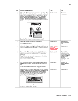
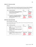
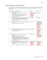
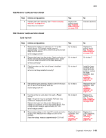
5061 Step 4 Actions and questions Check the printer is setting on a solid, flat surface. Is the printer setting on a solid, flat surface? 5 The front contamination shield is attached to the front plate of the ITU frame and lies on the top of the ITU belt. Is the front contamination shield lying on the ITU belt. 6 Remove the ITU and check the ITU belt position. If the belt has shifted to the front or to the rear it should be replaced. The belt must not shift more than 4 mm in either direction. Check by making the measurements as shown. The lower limit is 3.1 mm, the high limit is 8.1 mm, and the optimum position is 5.6 mm. Yes Go to step 5 Go to step 6 Replace the ITU assembly. See "ITU assembly removal" on page 4-49 and run the belt tracking. See "Belt Tracking (ITU 4th point adjustment)" on page 3-13. No Inform the customer that the printer must be setting on a solid, flat surface. Position the shield on top of the belt. Treat as a belt stall or signal communications problem. See "100.01 ITU error service check" on page 2-14. Has the ITU Belt shifted to the front or to the rear? 122.01 error code service check Hot fuser Error code 122.01 indicates that the fuser heated up too quickly or not quickly enough. Error code 122.01 may also indicate a problem in the fuser assembly with the hot roll bearings, hot roll thermistor, LVPS, or the system board. Step 1 Actions and questions Turn the printer on. Open the right side fuser access door. Observe the hot roll lamp to see if it turns on and off. You may have to observe the lamp for a few minutes to see if it turns on and off. Does the lamp turn on and off? 2 Turn the printer on. Measure the voltage on connector J17-11 on the system board. The voltage should measure approximately +0.13 V dc and +0.64 V dc as the hot roll lamp turns on and off. Is the voltage correct? Yes Go to step 2 Replace the fuser assembly. See "Fuser assembly removal" on page 4-44. No Replace the LVPS assembly. See "LVPS assembly removal" on page 4-53. Replace the system board. See "System board removal" on page 4-89. 2-18 Service Manual
-
 1
1 -
2
-
3
-
4
-
5
-
6
-
7
-
8
-
9
-
10
-
11
-
12
-
13
-
14
-
15
-
16
-
17
-
18
-
19
-
20
-
21
-
22
-
23
-
24
-
25
-
26
-
27
-
28
-
29
-
30
-
31
-
32
-
33
-
34
-
35
-
36
-
37
-
38
-
39
-
40
-
41
-
42
-
43
-
44
-
45
-
46
-
47
-
48
-
49
-
50
-
51
-
52
-
53
-
54
-
 55
55 -
 56
56 -
 57
57 -
 58
58 -
 59
59 -
 60
60 -
 61
61 -
 62
62 -
 63
63 -
 64
64 -
 65
65 -
66
-
67
-
68
-
69
-
70
-
71
-
72
-
73
-
74
-
75
-
76
-
77
-
78
-
79
-
80
-
81
-
82
-
83
-
84
-
85
-
86
-
87
-
88
-
89
-
90
-
91
-
92
-
93
-
94
-
95
-
96
-
97
-
98
-
99
-
100
-
101
-
102
-
103
-
104
-
105
-
106
-
107
-
108
-
109
-
110
-
111
-
112
-
113
-
114
-
115
-
116
-
117
-
118
-
119
-
120
-
121
-
122
-
123
-
124
-
125
-
126
-
127
-
128
-
129
-
130
-
131
-
132
-
133
-
134
-
135
-
136
-
137
-
138
-
139
-
140
-
141
-
142
-
143
-
144
-
145
-
146
-
147
-
148
-
149
-
150
-
151
-
152
-
153
-
154
-
155
-
156
-
157
-
158
-
159
-
160
-
161
-
162
-
163
-
164
-
165
-
166
-
167
-
168
-
169
-
170
-
171
-
172
-
173
-
174
-
175
-
176
-
177
-
178
-
179
-
180
-
181
-
182
-
183
-
184
-
185
-
186
-
187
-
188
-
189
-
190
-
191
-
192
-
193
-
194
-
195
-
196
-
197
-
198
-
199
-
200
-
201
-
202
-
203
-
204
-
205
-
206
-
207
-
208
-
209
-
210
-
211
-
212
-
213
-
214
-
215
-
216
-
217
-
218
-
219
-
220
-
221
-
222
-
223
-
224
-
225
-
226
-
227
-
228
-
229
-
230
-
231
-
232
-
233
-
234
-
235
-
236
-
237
-
238
-
239
-
240
-
241
-
242
-
243
-
244
-
245
-
246
-
247
-
248
-
249
-
250
-
251
-
252
-
253
-
254
-
255
-
256
-
257
-
258
-
259
-
260
-
261
-
262
-
263
-
264
-
265
-
266
-
267
-
268
-
269
-
270
-
271
-
272
-
273
-
274
-
275
-
276
-
277
-
278
-
279
-
280
-
281
-
282
-
283
-
284
-
285
-
286
-
287
-
288
-
289
-
290
-
291
-
292
-
293
-
294
-
295
-
296
-
297
-
298
-
299
-
300
-
301
-
302
-
303
-
304
-
305
-
306
-
307
-
308
-
309
-
310
-
311
-
312
-
313
-
314
-
315
-
316
-
317
-
318
-
319
-
320
-
321
-
322
-
323
-
324
-
325
-
326
-
327
-
328
-
329
-
330
-
331
-
332
-
333
-
334
-
335
-
336
-
337
-
338
-
339
-
340
-
341
-
342
-
343
-
344
-
345
-
346
-
347
-
348
-
349
-
350
-
351
-
352
-
353
-
354
-
355
-
356
-
357
-
358
-
359
-
360
-
361
-
362
-
363
-
364
-
365
-
366
-
367
-
368
-
369
-
370
-
371
-
372
-
373
-
374
-
375
-
376
-
377
-
378
-
379
-
380
-
381
-
382
-
383
-
384
-
385
-
386
-
387
-
388
-
389
-
390
-
391
-
392
-
393
-
394
-
395
-
396
-
397
-
398
-
399
-
400
-
401
-
402
-
403
-
404
-
405
-
406
-
407
-
408
-
409
-
410
-
411
-
412
-
413
-
414
-
415
-
416
-
417
-
418
-
419
-
420
-
421
-
422
-
423
-
424
-
425
-
426
-
427
-
428
-
429
-
430
-
431
-
432
-
433
-
434
-
435
-
436
-
437
-
438
-
439
-
440
-
441
-
442
-
443
-
444
-
445
-
446
-
447
-
448
-
449
-
450
-
451
-
452
-
453
-
454
-
455
-
456
-
457
-
458
-
459
-
460
-
461
-
462
-
463
-
464
-
465
-
466
-
467
-
468
-
469
-
470
-
471
-
472
-
473
-
474
 |
 |
