Pioneer SC-27 Owner's Manual - Page 38
MULTI-ZONE setup, Making MULTI-ZONE connections, Sub Zone, Input functions available
 |
UPC - 012562957487
View all Pioneer SC-27 manuals
Add to My Manuals
Save this manual to your list of manuals |
Page 38 highlights
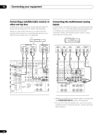
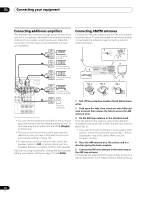
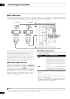
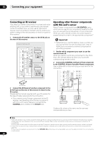
03 Connecting your equipment MULTI-ZONE setup This receiver can power up to three independent systems in separate rooms after you have made the proper MULTIZONE connections. An example MULTI-ZONE setup is shown below, but the number of MULTI-ZONE connections (and the way you choose to connect them) depends on how you want to set up your system. Sub zone (ZONE 3) Sub zone (ZONE 2) Main zone VIDEO IN AUDIO IN R L VIDEO IN AUDIO IN R L HDMI OUT 1 (KURO LINK ) OUT 2 XM IN COAXIAL ASSIGNABLE IN 1 (DVD) IN 2 (CD) BD IN IN 1 IN 2 IN 3 ASSIGNABLE 1-3 LAN (10/100) IN 3 (VIDEO 2) IN 1 (TV/SAT) IN 2 (DVR) IN 3 (VIDEO1) IN 4 (CD-R) ASSIGNABLE OUT 1 OUT 2 OPTICAL 12 V 1 IN 1 TRIGGER (OUTPUT 12V (DVD) (DVR TOTAL 50 mA MAX) 2 PR PB Y ZONE 2 OUT PR SIRIUS SI G IN IR IN 1 IN 2 OUT IN CONTROL OUT VIDEO ZONE 2 ZONE 3 PH OUT OUT L R SPEAKERS SELECTABLE SEE INSTRUCTION MANUAL CAUTION: SPEAKER IMPEDA ATTENTIO ENCEINTE D'IMPE SELECTABLE VOIR LE MODE D'EMPLOI RS-232C Different sources can be playing in three zones at the same time or, depending on your needs, the same source can also be used. The main and sub zones have independent power (the main zone power can be off while one (or both) of the sub zones is on) and the sub zones can be controlled by the remote or front panel controls. However, you may need to specify the volume settings in ZONE Audio Setup on page 129. Making MULTI-ZONE connections It is possible to make these connections if you have a separate TV and speakers for your primary (ZONE 2) sub zone, and a separate TV and a separate amplifier1 (and speakers) for your secondary (ZONE 3) sub zone. You will also need a separate amplifier if you are not using the MULTI-ZONE setup using speaker terminals (ZONE 2) on page 39 for your primary sub zone. There are two primary sub zone setups possible with this system. Choose whichever works best for you. MULTI-ZONE listening options The following table shows the signals that can be output to ZONE 2 and ZONE 3: Sub Zone ZONE 2 ZONE 3 Input functions available Analog audio signals (AUDIO ZONE 2 OUT).a With video signals,b the composite video (VIDEO ZONE 2 OUT) and component video (COMPONENT VIDEO ZONE 2 OUT)c signals can be outputd but the S-Video signal cannot be output. Analog audio signals (AUDIO ZONE 3 OUT).a With video signals,b the composite video (VIDEO ZONE 3 OUT) signals can be output. a.Any analog signal. (This does not apply for the MULTI CH IN and PHONO inputs.) b.JPEG files cannot be played with the input set to USB input. c.The COMPONENT VIDEO ZONE 2 OUT jack is only provided on the SC-27. The OSD is not displayed if only the COMPONENT VIDEO ZONE 2 OUT jack is connected. d.SC-27 only: The video convert function does not work for ZONE 2. Connect the composite video and component video to the same types of jacks for the inputs and outputs. Note 1 You can't use sound controls (such as the tone controls or Midnight listening) or any surround modes with a separate amplifier in the sub zone. You can, however, use the features available with your sub zone amplifier. 38 en
-
 1
1 -
2
-
3
-
4
-
5
-
6
-
7
-
8
-
9
-
10
-
11
-
12
-
13
-
14
-
15
-
16
-
17
-
18
-
19
-
20
-
21
-
22
-
23
-
24
-
25
-
26
-
27
-
28
-
29
-
30
-
31
-
32
-
 33
33 -
 34
34 -
 35
35 -
 36
36 -
 37
37 -
 38
38 -
 39
39 -
 40
40 -
 41
41 -
 42
42 -
 43
43 -
44
-
45
-
46
-
47
-
48
-
49
-
50
-
51
-
52
-
53
-
54
-
55
-
56
-
57
-
58
-
59
-
60
-
61
-
62
-
63
-
64
-
65
-
66
-
67
-
68
-
69
-
70
-
71
-
72
-
73
-
74
-
75
-
76
-
77
-
78
-
79
-
80
-
81
-
82
-
83
-
84
-
85
-
86
-
87
-
88
-
89
-
90
-
91
-
92
-
93
-
94
-
95
-
96
-
97
-
98
-
99
-
100
-
101
-
102
-
103
-
104
-
105
-
106
-
107
-
108
-
109
-
110
-
111
-
112
-
113
-
114
-
115
-
116
-
117
-
118
-
119
-
120
-
121
-
122
-
123
-
124
-
125
-
126
-
127
-
128
-
129
-
130
-
131
-
132
-
133
-
134
-
135
-
136
-
137
-
138
-
139
-
140
-
141
-
142
-
143
-
144
-
145
-
146
-
147
-
148
-
149
-
150
-
151
-
152
-
153
-
154
 |
 |
