Pioneer VSX-49TX Owner's Manual - Page 30
What is i.LINK?, Connecting i.LINK-equipped Components - parts
 |
View all Pioneer VSX-49TX manuals
Add to My Manuals
Save this manual to your list of manuals |
Page 30 highlights
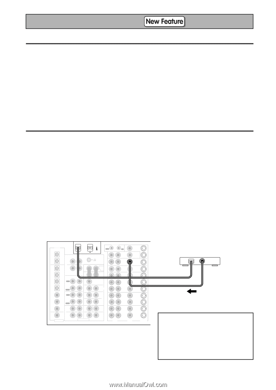
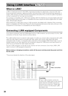
Using i.LINK Interface What is i.LINK? i.LINK is a trademark name for IEEE1394, a high-speed interface for digital audio, video and other data found on personal computers, digital camcorders, and other kinds of audio and audio/visual equipment. A single i.LINK connector can both send and receive data at the same time, so only one cable is required to connect components for two-way communication. This receiver is compatible with i.LINK Audio interface. With this interface you can enjoy digital audio from SACD and DVD-A discs (if the player is compatible with these outputs), as well as digital audio from DVDVideo, CD and Video CD discs. When playing CD or SACD discs over an i.LINK connection, the digital audio is jitterless if the connected player is compatible with PQLS (see PQLS p.5). See the operating instructions that came with your i.LINK components for information on compatibility with these features. Connecting i.LINK-equipped Components If you have a component (such as a DVD player) with an i.LINK connector, you can connect it to the i.LINK connectors on the rear of your receiver as shown below. The i.LINK interface does not transmit video signals. So when you connect video components with i.LINK cable, the video signal must be connected with other cables. Hook up the video signal with either component video, S video, or composite video cords (see p.19) to available VIDEO IN terminals. If you've already hooked up the video signal from the component, assign the i.LINK input to the input function to which you've connected the video signals (see p.95). The two i.LINK connectors on the rear of your receiver are 4-pin connectors. Use a 4-pin, S400 i.LINK cable to connect i.LINK-equipped components. Before making or changing connections, switch off the power and disconnect the power cord from the AC outlet. *The arrows indicate the direction of the video signal. 30 DIGITAL PCM/2DIGITAL /DTS 2 OUT S400 (AUDIO) OUT 1 PHONO R AUDIO L OUT IN 7 (CD-R/ CD TAPE1 IN /MD) IN 6 (VCR2) IN R 5 OUT (VCR1 REC IN /DVR) CD-R/ TAPE1 4 /MD (SAT) IN IN PLAY 3 IN OUT (CD) REC TAPE2 MONITOR 2 IN (TV) IN PLAY 1 IN (DVD /LD) 2RF IN (DVD /LD) (For LD) ASSIGNABLE FRONT R SURROUND R AUDIO POWER AMP R L IN FRONT L R L CENTER 1 (Single) R R SUB W. L LR MULTI CH INPUT SUB W. PRE OUT 2 SURROUND L SURROUND BACK L (Single) CENTER SURROUND BACK L (Single) CONTROL IN MULTIROOM & SOURCE DVD /LD IN TV IN SAT IN OUT VCR1 /DVR IN MONITOR OUT OUT IN IN IN OUT IN OUT OUT VCR2 IN IN R L AUDIO OUT VCR3 IN VIDEO OUT IN S2 VIDEO i.LINK component i.LINK connection Video connection CAUTION: If your i.LINK connector comes into contact with metallic parts of the receiver other than the intended connector an electrical short may occur. Please take care to connect it to the proper i.LINK connector only.
-
 1
1 -
2
-
3
-
4
-
5
-
6
-
7
-
8
-
9
-
10
-
11
-
12
-
13
-
14
-
15
-
16
-
17
-
18
-
19
-
20
-
21
-
22
-
23
-
24
-
 25
25 -
 26
26 -
 27
27 -
 28
28 -
 29
29 -
 30
30 -
 31
31 -
 32
32 -
 33
33 -
 34
34 -
 35
35 -
36
-
37
-
38
-
39
-
40
-
41
-
42
-
43
-
44
-
45
-
46
-
47
-
48
-
49
-
50
-
51
-
52
-
53
-
54
-
55
-
56
-
57
-
58
-
59
-
60
-
61
-
62
-
63
-
64
-
65
-
66
-
67
-
68
-
69
-
70
-
71
-
72
-
73
-
74
-
75
-
76
-
77
-
78
-
79
-
80
-
81
-
82
-
83
-
84
-
85
-
86
-
87
-
88
-
89
-
90
-
91
-
92
-
93
-
94
-
95
-
96
-
97
-
98
-
99
-
100
-
101
-
102
-
103
-
104
-
105
-
106
-
107
-
108
-
109
-
110
-
111
-
112
-
113
-
114
-
115
-
116
-
117
-
118
-
119
-
120
 |
 |