Pioneer VSX-49TX Owner's Manual - Page 35
Multi-room & Source Remote
 |
View all Pioneer VSX-49TX manuals
Add to My Manuals
Save this manual to your list of manuals |
Page 35 highlights
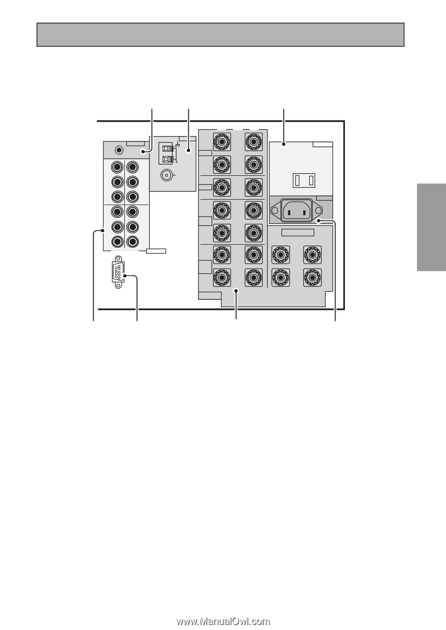
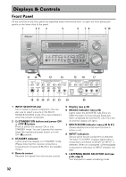
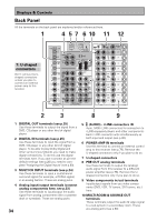
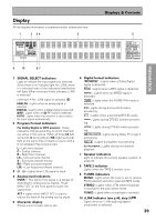
Displays & Controls PREPARATION PREPARATION 13 16 19 DVD /LD IN 1 Y PB PR IN 2 Y REMOTE IN MULTIROOM & SOURCE Y MONITOR OUT PB PR IN 3 Y PB PB PR PR COMPONENT VIDEO ASSIGNABLE RS-232C ·Åª ANTENNA L AM LOOP ANTENNA FM 75Ω UNBAL FRONT R CENTER L SURROUND R L SURROUND BACK R (Single) SPEAKERS AC OUTLET AC IN SPEAKERS ª ı· L R 14 15 17 18 11 CONTROL IN/OUT terminal You can use this jack to hook up other PIONEER equipment, with a CONTROL terminal, so that you can control them all pointing the remote control(s) at one remote sensor. 12 MONITOR OUT terminals (connect a TV or monitor here, see p.13 & 19) Use these terminals to output a video signal to a TV or monitor. 13 MULTI-ROOM & SOURCE REMOTE IN terminals (see p.80) Use these terminals to hook up a sub-system in a secondary room. This hook up requires a separately sold IR receiver and allows you to use the receiver to view and hear different sources in different rooms. 14 COMPONENT VIDEO terminals Use these terminals to hook up the video connections of your video components with this high quality method. Your components will have to have the terminals as well to take advantage of this kind of connection. See p.19 for more on setting up your receiver for component video. If you use these terminals you need to complete "Assigning the Component Video Inputs" (see p.94). 15 RS-232C Connection This is a future-oriented port that has the possibility on inputting and/or outputting information to/from the receiver. 16 Radio antenna terminals Hook up antennas for the radio tuner built into the receiver here. 17 SPEAKER terminals Use these terminals to connect speakers to the receiver (see p.14, 28, 76 & 79). There are two speaker systems on this receiver A & B. The A system is the one that handles surround sound and is fed by the surround and surround back speakers. If you want to use alternative speaker connections like bi-amping or bi-wiring see p.76. 18 AC IN (Power In) Hook up the power cord to this terminal. 19 AC outlet (Switched 100 W max.) Hook up an external component to the power supply of this receiver. Only do this with audio or video components being used in this system and never hook up heavy equipment (like TVs, heaters, air conditioners, refrigerators, etc.) to this receiver. 35
-
 1
1 -
2
-
3
-
4
-
5
-
6
-
7
-
8
-
9
-
10
-
11
-
12
-
13
-
14
-
15
-
16
-
17
-
18
-
19
-
20
-
21
-
22
-
23
-
24
-
25
-
26
-
27
-
28
-
29
-
 30
30 -
 31
31 -
 32
32 -
 33
33 -
 34
34 -
 35
35 -
 36
36 -
 37
37 -
 38
38 -
 39
39 -
 40
40 -
41
-
42
-
43
-
44
-
45
-
46
-
47
-
48
-
49
-
50
-
51
-
52
-
53
-
54
-
55
-
56
-
57
-
58
-
59
-
60
-
61
-
62
-
63
-
64
-
65
-
66
-
67
-
68
-
69
-
70
-
71
-
72
-
73
-
74
-
75
-
76
-
77
-
78
-
79
-
80
-
81
-
82
-
83
-
84
-
85
-
86
-
87
-
88
-
89
-
90
-
91
-
92
-
93
-
94
-
95
-
96
-
97
-
98
-
99
-
100
-
101
-
102
-
103
-
104
-
105
-
106
-
107
-
108
-
109
-
110
-
111
-
112
-
113
-
114
-
115
-
116
-
117
-
118
-
119
-
120
 |
 |