Pioneer VSX-49TX Owner's Manual - Page 33
Preparation
 |
View all Pioneer VSX-49TX manuals
Add to My Manuals
Save this manual to your list of manuals |
Page 33 highlights
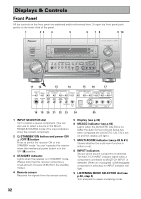
PREPARATION PREPARATION 10 MASTER VOLUME dial Adjusts the overall receiver volume. 11 ACOUSTIC CAL. button (see p.56) Use to switch on and off the Acoustic Calibration EQ. 12 MIDNIGHT button (see p.57) Use to switch the receiver into MIDNIGHT mode. 13 TONE control buttons (see p.58) TONE button This button switches between TONE ON and TONE BYPASS, which bypasses the tone circuitry. BASS/TREBLE button Use to select whether the bass or treble will be adjusted.. (-/+) buttons Use to adjust the frequency levels. 14 DIGITAL NR button (see p.56) Switches the DIGITAL NR on or off. 15 TUNER CONTROL buttons (see p.64-68) CLASS button - Press repeatedly to switch the preset station classes. -/+ button - Use to choose programmed radio stations. 16 LISTENING CH SELECT button (see p.49, 59 & 60) Use this button to select the number of channels used for playback (5.1, 7.1, or AUTO). 17 MULTI-ROOM & SOURCE buttons (see p.80-84) Press to use the multi room feature (requires an optional PIONEER Multi-Room Remote Sensor Unit MR-100 or another IR receiver). CONTROL button: Used together with the INPUT SELECTOR to select the function or use with the MASTER VOLUME to select the volume of the MULTI ROOM system. ON/OFF button: Use to switch Multi-room function on or off. 18 PHONES jack Connect headphones for private listening (no sound will be heard through the speakers). Displays & Controls 19 SP SYSTEM A/B button (see p.77) Use to select the speaker system. A is the primary setting. The button cycles through the speaker systems as follows: A]B]A&B]off. Different conditions apply when bi-amping the speakers. For this case refer to page 76. 20 SIGNAL SELECT button (see p.51) Use to select the type of signal being input into the receiver. Depending on your INPUT ASSIGN settings (see pages 93-96) available inputs will change. Since there is no indicator light for i.LINK, when it is selected none of the indicators listed below will light. When none are lit this indicates i.LINK is selected. Press SIGNAL SELECT repeatedly to select one of the following: ANALOG - To select an analog signal. DIGITAL - To select an optical or coaxial digital signal. nothing lit - To select an i.LINK signal. 2 RF - To select an 2 RF signal. AUTO - This is the default setting. The receiver selects a signal based on availability, in the following order of priority: i.LINK, 2 RF, DIGITAL, ANALOG. 21 VIDEO SELECT button (see p.61) Switches the receiver between the various types of video input. 22 TAPE 2 MONITOR button Selects the tape deck (MD recorder, etc.) connected to the TAPE 2 MONITOR inputs/ outputs. Allows monitoring of a recording as it's being made. 23 MULTI CH INPUT button Selects the component (for example, a DVD-A player) you have hooked up to the MULTI CH INPUT terminals. 24 SETUP MIC jack Plug in the setup mic here. This is very important for setting up your system to get proper surround sound. 25 Front VIDEO INPUT jacks (see p.21) DIGITAL IN : digital input for connecting a game console, portable DVD player, video camera (etc.), that has an optical digital connection. S VIDEO : Video input for connecting a video camera (etc.), that has an S video out. RCA VIDEO / AUDIO (L/R) : Video/audio input for connecting a video camera, etc. that has standard RCA video/audio outputs. 33
-
 1
1 -
2
-
3
-
4
-
5
-
6
-
7
-
8
-
9
-
10
-
11
-
12
-
13
-
14
-
15
-
16
-
17
-
18
-
19
-
20
-
21
-
22
-
23
-
24
-
25
-
26
-
27
-
 28
28 -
 29
29 -
 30
30 -
 31
31 -
 32
32 -
 33
33 -
 34
34 -
 35
35 -
 36
36 -
 37
37 -
 38
38 -
39
-
40
-
41
-
42
-
43
-
44
-
45
-
46
-
47
-
48
-
49
-
50
-
51
-
52
-
53
-
54
-
55
-
56
-
57
-
58
-
59
-
60
-
61
-
62
-
63
-
64
-
65
-
66
-
67
-
68
-
69
-
70
-
71
-
72
-
73
-
74
-
75
-
76
-
77
-
78
-
79
-
80
-
81
-
82
-
83
-
84
-
85
-
86
-
87
-
88
-
89
-
90
-
91
-
92
-
93
-
94
-
95
-
96
-
97
-
98
-
99
-
100
-
101
-
102
-
103
-
104
-
105
-
106
-
107
-
108
-
109
-
110
-
111
-
112
-
113
-
114
-
115
-
116
-
117
-
118
-
119
-
120
 |
 |