Brother International LT2-B878 Instruction Manual - English and Spanish - Page 79
Stellen Sie den Abstand zwischen der Nadel
 |
View all Brother International LT2-B878 manuals
Add to My Manuals
Save this manual to your list of manuals |
Page 79 highlights
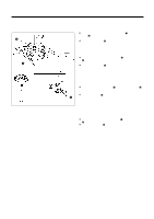
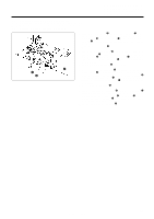
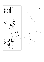
[B878] e A D C D B (-305 specifications only) (Nur Ausführung -305) (spécifications -305 seulement) (Solo para especificaciones -305) C 10. STANDARD ADJUSTMENTS 10. STANDARDEINSTELLUNGEN 10. REGLAGES STANDARD 10. AJUSTES ESTANDARES s B878 1. Tilt back the machine head. 2. Loosen screws A, B and C (and also screw D for -305 speci- fications). 3. Move the rotary hook base e to the left and right to set e the gap between the needle q and the tip of the rotary hook w to 0.05 mm. 4. After adjusting, securely tighten screws A, B and C (and also screw D for -305 specifications). NOTE: Be careful not to move the screw stop position when tightening screw C. 5. For -305 specifications, carry out the steps in "Thread trimming cam adjustment" on page 89. s B878 1. Klappen Sie das Maschinenoberteil zurück. 2. Lösen Sie die Schrauben A, B und C (und für die Ausführung -305 auch die Schraube D). 3. Stellen Sie den Abstand zwischen der Nadel q und der Greiferspitze w durch seitliches Verschieben der Greiferbasis e auf 0,05 mm ein. 4. Ziehen Sie nach dem Einstellen die Schrauben A, B und C (und für die Ausführung -305 auch die Schraube D) wieder fest. HINWEIS: Beim Festziehen der Schraube C darf die Schraubenanschlagposition nicht verschoben werden. 5. Führen Sie für die Ausführung -305 die Schritte im Abschnitt "Einstellen des Fadenabschneidernockens" auf Seite 89 aus. s B878 1. Incliner la tête de machine vers l'arrière. 2. Desserrer les vis A, B et C (et aussi la vis D pour les spécifications -305). 3. Déplacer la base e du crochet rotatif vers la gauche et la droite de manière que l'écart entre l'aiguille q et la pointe du crochet rotatif w soit de 0,05 mm. 4. Une fois le réglage effectué, bien resserrer les vis A, B et C (et aussi la vis D pour les spécifications -305). REMARQUE: Veiller à ne pas déplacer la position d'arrêt de la vis lorsqu'on serre la vis C. 5. Pour les spécifications -305, effectuer les étapes de la section "Réglage de la came de coupe des fils" de la page 89. s B878 1. Inclinar hacia atrás la cabeza de la máquina. 2. Aflojar los tornillos A, B y C (y también el tornillo D para las especificaciones -305). 3. Mover la base del garfio giratorio e hacia la izquierda y la derecha para ajustar la separación entre la aguja q y la punta del garfio giratorio w a 0,05 mm. 4. Después de ajustar, apretar firmemente los tornillos (A, B y C (y también el tornillo D para las especificaciones -305). NOTA: Tener cuidado de no mover la posición de parada del tornillo al apretar el tornillo C. 5. Para las especificaciones -305, realizar los pasos en la sección "Ajuste de la leva de cortahilos" en la página 89. 60 LS2-B877, LT2-B878
-
 1
1 -
2
-
3
-
4
-
5
-
6
-
7
-
8
-
9
-
10
-
11
-
12
-
13
-
14
-
15
-
16
-
17
-
18
-
19
-
20
-
21
-
22
-
23
-
24
-
25
-
26
-
27
-
28
-
29
-
30
-
31
-
32
-
33
-
34
-
35
-
36
-
37
-
38
-
39
-
40
-
41
-
42
-
43
-
44
-
45
-
46
-
47
-
48
-
49
-
50
-
51
-
52
-
53
-
54
-
55
-
56
-
57
-
58
-
59
-
60
-
61
-
62
-
63
-
64
-
65
-
66
-
67
-
68
-
69
-
70
-
71
-
72
-
73
-
 74
74 -
 75
75 -
 76
76 -
 77
77 -
 78
78 -
 79
79 -
 80
80 -
 81
81 -
 82
82 -
 83
83 -
 84
84 -
85
-
86
-
87
-
88
-
89
-
90
-
91
-
92
-
93
-
94
-
95
-
96
-
97
-
98
-
99
-
100
-
101
-
102
-
103
-
104
-
105
-
106
-
107
-
108
-
109
-
110
-
111
-
112
-
113
-
114
-
115
-
116
-
117
-
118
-
119
-
120
-
121
-
122
-
123
-
124
-
125
-
126
-
127
-
128
-
129
-
130
-
131
-
132
-
133
-
134
-
135
 |
 |
