Brother International LT2-B878 Instruction Manual - English and Spanish - Page 83
Entfernen Sie den Transporteur.
 |
View all Brother International LT2-B878 manuals
Add to My Manuals
Save this manual to your list of manuals |
Page 83 highlights
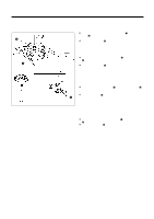
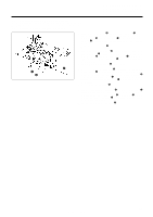
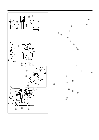
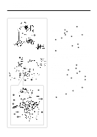
(a) w (b) q [B877] [B878] r Center of needle Nadelmitte 1 - 1.5 mm 1 - 1,5 mm 2.4 mm 2,4 mm Needle down position Heruntergestellte Nadel t y u t y 10. STANDARD ADJUSTMENTS 10. STANDARDEINSTELLUNGEN 10. REGLAGES STANDARD 10. AJUSTES ESTANDARES s Needle bar lift amount 7. Remove the needle plate. 8. Remove the feed dog. 9. Set the feed adjustment dial to the minimum setting. 10. Turn the machine pulley to raise the needle bar q 2.4 mm from its lowest position. 11. Reference line (b) on the needle bar will be almost aligned with the bottom edge of the needle bar bracket w. The tip of the rotary hook r must be aligned with the center of the needle at this time. 12. Tilt back the machine head. 13. Loosen the set screw t, and then move the lower shaft gear y to the left and right to align the tip of the rotary hook r with the center of the needle. * The rotary hook shaft has a screw stop on it, and so the pinion gear u cannot be used to make the adjustment. 14. Tighten the set screw t. * Be careful not to move the screw stop position when tightening the set screw t. 15. The clearance between the top edge of the needle hole and the tip of the rotary hook r must be 1 - 1.5 mm when the tip of the rotary hook r is aligned with the center of the needle. 16. Install the feed dog. 17. Install the needle plate. s Nadelstangenhub 7. Entfernen Sie die Stichplatte. 8. Entfernen Sie den Transporteur. 9. Stellen Sie die Transporteinstellscheibe auf die Minimalposition ein. 10. Heben Sie die Nadelstange q durch Drehen der Riemenscheibe um 2,4 mm von der untersten Position an. 11. Die Bezugslinie (b) an der Nadelstange q ist beinahe auf die untere Kante der Nadelstangenhalterung w ausgerichtet. Die Greiferspitze r muß auf die Nadelmitte ausgerichtet sein. 12. Klappen Sie das Maschinenoberteil zurück. 13. Lösen Sie die Schraube t und verschieben Sie das untere Wellenrad y zum Ausrichten der Greiferspitze r auf die Nadel nach links oder rechts. * Auf der Greiferwelle ist ein Schraubenanschlag vorhanden, so daß sich die Einstellung nicht mit dem Antriebsrad u vornehmen läßt. 14. Ziehen Sie die Schraube t wieder fest. * Beim Festziehen der Schraube t darf die Schraubenanschlagposition nicht verschoben werden. 15. Der Abstand zwischen der oberen Nadellochkante und der Greiferspitze r muß 1 - 1,5 mm betragen, wenn die Greiferspitze r auf die Nadelmitte ausgerichtet ist. 16. Installieren Sie den Transporteur. 17. Bringen Sie die Stichplatte wieder an. y t y 64 LS2-B877, LT2-B878
-
 1
1 -
2
-
3
-
4
-
5
-
6
-
7
-
8
-
9
-
10
-
11
-
12
-
13
-
14
-
15
-
16
-
17
-
18
-
19
-
20
-
21
-
22
-
23
-
24
-
25
-
26
-
27
-
28
-
29
-
30
-
31
-
32
-
33
-
34
-
35
-
36
-
37
-
38
-
39
-
40
-
41
-
42
-
43
-
44
-
45
-
46
-
47
-
48
-
49
-
50
-
51
-
52
-
53
-
54
-
55
-
56
-
57
-
58
-
59
-
60
-
61
-
62
-
63
-
64
-
65
-
66
-
67
-
68
-
69
-
70
-
71
-
72
-
73
-
74
-
75
-
76
-
77
-
 78
78 -
 79
79 -
 80
80 -
 81
81 -
 82
82 -
 83
83 -
 84
84 -
 85
85 -
 86
86 -
 87
87 -
 88
88 -
89
-
90
-
91
-
92
-
93
-
94
-
95
-
96
-
97
-
98
-
99
-
100
-
101
-
102
-
103
-
104
-
105
-
106
-
107
-
108
-
109
-
110
-
111
-
112
-
113
-
114
-
115
-
116
-
117
-
118
-
119
-
120
-
121
-
122
-
123
-
124
-
125
-
126
-
127
-
128
-
129
-
130
-
131
-
132
-
133
-
134
-
135
 |
 |
