Brother International LT2-B878 Instruction Manual - English and Spanish - Page 90
Réglage de la synchronisation de l'arbre supérieur et inférieur
 |
View all Brother International LT2-B878 manuals
Add to My Manuals
Save this manual to your list of manuals |
Page 90 highlights
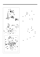
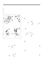
10. STANDARD ADJUSTMENTS 10. STANDARDEINSTELLUNGEN 10. REGLAGES STANDARD 10. AJUSTES ESTANDARES 10-8. Upper and lower shaft timing adjustment 10-8. Einstellung des Gleichlaufs der oberen und unteren Welle 10-8. Réglage de la synchronisation de l'arbre supérieur et inférieur 10-8. Ajuste de la sincronización de los ejes superior e inferior q Red dot Roter Punkt Point rouge Punto rojo T 2 mm [-305] s Checking the thread trimmer timing 1. Remove the needle. 2. Tilt back the machine head. 3. Hold the thread trimming solenoid q depressed and turn the machine pulley in its normal direction of rotation until w the pulley starts to become hard to turn (the movable knife will begin to move). e 4. The standard position is when the T mark on the machine pulley scale is 2 mm forward of the red dot on the machine head. (The allowable range for the T mark position at this r time is within 0 to 4 mm away from the red dot.) * If adjustment is necessary, follow the steps given below. s Upper and lower shaft timing adjustment (Thread trimmer timing adjustment) 1. Remove the timing belt w. 2. Turn the machine pulley until the T mark on the scale is 2 mm forward of the red dot. 3. Hold the thread trimming solenoid q depressed and turn timing pulley D e in the direction of the arrow until it starts to become hard to move. 4. Set the machine pulley and timing pulley D e so that they cannot move, and then attach the timing belt w. 5. Check the T mark on the machine pulley scale once more. * Do not change the position of the set screw r under any circumstances. 6. Install the needle. s Kontrolle des Fadenabschneidezeitpunkts 1. Entfernen Sie die Nadel. 0 - 4 mm 2. Klappen Sie das Maschinenoberteil zurück. 3. Halten Sie den Fadenabschneidemagnet q gedrückt und Allowable range zulässiger Bereich Plage acceptable Rango permitido drehen Sie die Riemenscheibe in der normalen Drehrichtung, bis ein Widerstand spürbar ist (Bewegung des beweglichen Messers). 4. Die Standardposition ist, wenn sich die Markierung "T" der Riemenscheibe 2 mm vor dem roten Punkt auf dem Maschinenonerteil befindet. (Der zulässige Bereich für die Markierung "T" ist innerhalb von 0 bis 4 mm vom roten Punkt.) * Notwendigenfalls können Sie eine Einstellung wie folgt vornehmen. s Einstellung der Synchronisation zwischen der oberen und unteren Welle (Einstellen des Fadenabschneidezeitpunkts) 1. Entfernen Sie den Steuerriemen w. 2. Drehen Sie die Riemenscheibe, so daß sich die Markierung "T" auf der Skala 2 mm vor dem roten Punkt befindet. 3. Halten Sie den Fadenabschneidemagnet q gedrückt und drehen Sie die Riemenscheibe D e in Pfeilrichtung, bis ein Widerstand verspürt wird. 4. Blockieren Sie die Riemenscheibe und die Steuerscheibe D e und bringen Sie den Steuerriemen an w an. 5. Kontrollieren Sie die Markierung "T" auf der Riemenscheibenskala nochmals. * Die Position der Schrauben r darf unter keinen Umständen geändert werden. 6. Installieren Sie die Nadel. s Vérification de la synchronisation du coupe-fils 1. Déposer l'aiguille. 2. Incliner la tête de machine vers l'arrière. 3. Maintenir le solénoïde de coupe-fils q enfoncé et tourner la poulie de machine dans son sens de rotation normal jusqu'à ce que la poulie commence à devenir dure à tourner (le couteau mobile commence alors à bouger). 4. La position normale est lorsque le repère T marqué sur l'échelle de la poulie de machine se trouve à 2 mm à l'avant du point rouge marqué sur la tête de machine. (La plage acceptable pour la position du repère T à ce moment se trouve entre 0 et 4 mm du point rouge.) * S'il est nécessaire d'effectuer un réglage, procéder comme indiqué ci-dessous. s Réglage de la synchronisation de l'arbre supérieur et inférieur (réglage de la synchronisation du coupe-fils) 1. Déposer la courroie de synchronisation w. 2. Tourner la poulie de machine jusqu'à ce que le repère T marqué sur l'échelle soit situé à 2 mm à l'avant du point rouge. 3. Maintenir le solénoïde du coupe-fils q enfoncé et tourner la poulie de synchronisation D e dans le sens de la flèche jusqu'à ce qu'elle devienne difficile à bouger. 4. Régler la poulie de machine et la poulie de synchronisation D e de manière qu'elles ne puissent plus bouger, puis fixer la courroie de synchronisation w. 5. Vérifier à nouveau l'emplacement du repère T sur l'échelle de la poulie de machine. * Veiller absolument à ne pas modifier la position de la vis de réglage r. 6. Installer l'aiguille. 71 LS2-B877, LT2-B878
-
 1
1 -
2
-
3
-
4
-
5
-
6
-
7
-
8
-
9
-
10
-
11
-
12
-
13
-
14
-
15
-
16
-
17
-
18
-
19
-
20
-
21
-
22
-
23
-
24
-
25
-
26
-
27
-
28
-
29
-
30
-
31
-
32
-
33
-
34
-
35
-
36
-
37
-
38
-
39
-
40
-
41
-
42
-
43
-
44
-
45
-
46
-
47
-
48
-
49
-
50
-
51
-
52
-
53
-
54
-
55
-
56
-
57
-
58
-
59
-
60
-
61
-
62
-
63
-
64
-
65
-
66
-
67
-
68
-
69
-
70
-
71
-
72
-
73
-
74
-
75
-
76
-
77
-
78
-
79
-
80
-
81
-
82
-
83
-
84
-
 85
85 -
 86
86 -
 87
87 -
 88
88 -
 89
89 -
 90
90 -
 91
91 -
 92
92 -
 93
93 -
 94
94 -
 95
95 -
96
-
97
-
98
-
99
-
100
-
101
-
102
-
103
-
104
-
105
-
106
-
107
-
108
-
109
-
110
-
111
-
112
-
113
-
114
-
115
-
116
-
117
-
118
-
119
-
120
-
121
-
122
-
123
-
124
-
125
-
126
-
127
-
128
-
129
-
130
-
131
-
132
-
133
-
134
-
135
 |
 |
