Dell OptiPlex Gs Reference and Installation Guide (.pdf) - Page 62
Replacing the Expansion-Card Cage, Inside Your Computer, Jumpers
 |
View all Dell OptiPlex Gs manuals
Add to My Manuals
Save this manual to your list of manuals |
Page 62 highlights
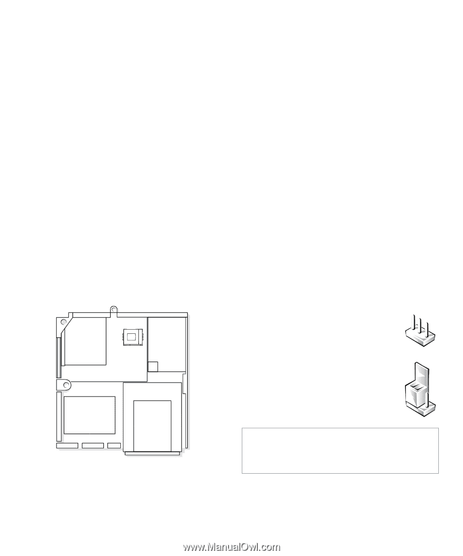
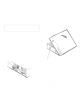
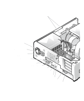
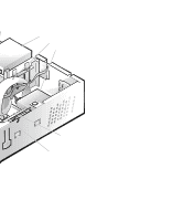
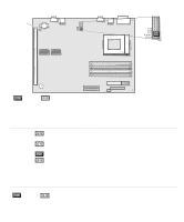
Replacing the Expansion-Card Cage Use the following procedure to replace the expansioncard cage: 1. With the securing lever in the upright position, align the slots in the left side of the expansioncard cage with the tabs on the left side of the chassis (see Figure 5-4). Then lower the expansion-card cage into place. 2. Rotate the securing lever downward until it is flush with the top of the chassis. Make sure the riser board is fully seated in the RISER connector on the system board. 3. Reconnect any cables you removed in step 2 of the previous procedure, "Removing the ExpansionCard Cage." Inside Your Computer Figure 5-5 shows an overhead view of your computer to help you orient yourself when installing hardware options. Unless otherwise specified, locations or directions relative to the computer are as shown. back of computer expansioncard cage power supply system left board side hard-disk drive externally accessible drive bays right side front of computer Figure 5-5. Computer Orientation View Figure 5-6 shows your computer with its cover removed. Refer to this illustration to locate interior features and components discussed in this guide. When you look inside your computer, note the direct current (DC) power cables coming from the power supply. These cables supply power to the system board; to internal diskette drives, hard-disk drives, and tape drives; and to certain expansion cards that connect to external peripherals. The flat ribbon cable in Figure 5-6 is typical of the interface cables for internal drives. An interface cable connects a drive to a connector on the system board or on an expansion card. The system board-the large printed circuit board at the bottom of the chassis-holds the computer's control circuitry and other electronic components. Some hardware options are installed directly onto the system board. During an installation procedure, you may be required to change a jumper setting on the system board, and/or a jumper or switch setting on an expansion card or on a drive. Jumpers and switches provide a convenient and reversible way of reconfiguring the circuitry on a printed circuit board. For information on jumpers and switches, see the next two subsections, "Jumpers" and "Switches." Jumpers Jumpers are small blocks on a circuit board with two or more pins emerging from them. Plastic plugs containing a wire fit down over the pins. The wire connects the pins and creates a circuit. To change a jumper setting, pull the plug off its pin(s) and carefully fit it down onto the pin(s) indicated. CAUTION: Make sure your system is turned off before you change a jumper setting. Otherwise, damage to your system or unpredictable results may occur. 5-4 Dell OptiPlex Gs and Gs+ Low-Profile Systems Reference and Installation Guide
-
 1
1 -
2
-
3
-
4
-
5
-
6
-
7
-
8
-
9
-
10
-
11
-
12
-
13
-
14
-
15
-
16
-
17
-
18
-
19
-
20
-
21
-
22
-
23
-
24
-
25
-
26
-
27
-
28
-
29
-
30
-
31
-
32
-
33
-
34
-
35
-
36
-
37
-
38
-
39
-
40
-
41
-
42
-
43
-
44
-
45
-
46
-
47
-
48
-
49
-
50
-
51
-
52
-
53
-
54
-
55
-
56
-
 57
57 -
 58
58 -
 59
59 -
 60
60 -
 61
61 -
 62
62 -
 63
63 -
 64
64 -
 65
65 -
 66
66 -
 67
67 -
68
-
69
-
70
-
71
-
72
-
73
-
74
-
75
-
76
-
77
-
78
-
79
-
80
-
81
-
82
-
83
-
84
-
85
-
86
-
87
-
88
-
89
-
90
-
91
-
92
-
93
-
94
-
95
-
96
-
97
-
98
-
99
-
100
-
101
-
102
-
103
-
104
-
105
-
106
-
107
-
108
-
109
-
110
-
111
-
112
-
113
-
114
-
115
-
116
-
117
-
118
-
119
-
120
-
121
 |
 |