Dell OptiPlex Gs Reference and Installation Guide (.pdf) - Page 77
Pin-1 Identification, Installing the Microprocessor, chip is positioned correctly
 |
View all Dell OptiPlex Gs manuals
Add to My Manuals
Save this manual to your list of manuals |
Page 77 highlights
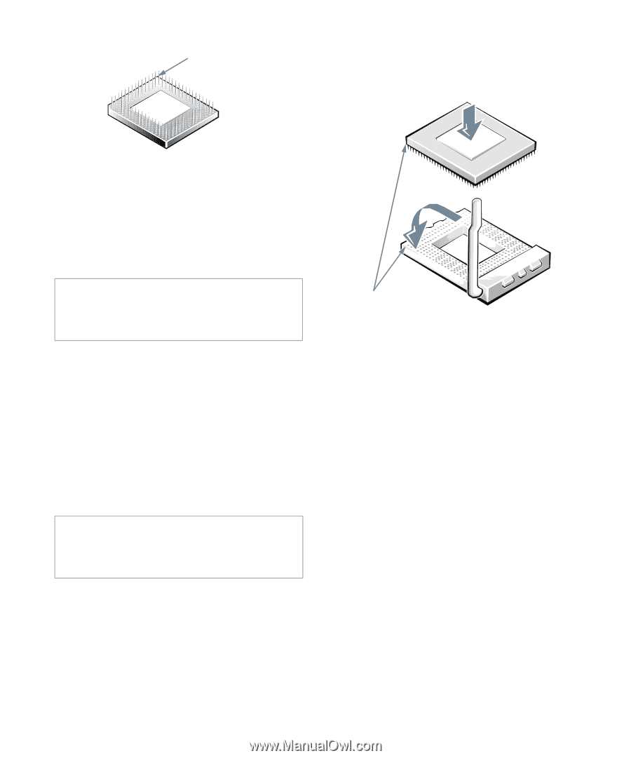
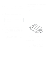
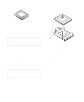
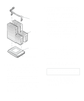
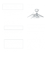
pin-1 corner (gold finger and square pad) When the chip is fully seated in the socket, pivot the microprocessor-socket release lever back down until it snaps into place, securing the chip. 1 Figure 6-11. Pin-1 Identification The pin-1 corner of the socket is the corner to your left and closest to the front of the chassis as you face the front of the computer (see Figure 6-1). 7. Install the microprocessor chip in the socket (see Figure 6-12). CAUTION: Positioning the microprocessor chip incorrectly in the socket can permanently damage the chip and the computer when you turn on the system. If the release lever on the microprocessor socket is not all the way up, move it to that position now. With the pin-1 corners of the chip and socket aligned, align the pins on the chip with the holes in the socket. Set the chip lightly in the socket and make sure all pins are headed into the correct holes. Because your system uses a ZIF microprocessor socket, there is no need to use force (which could bend the pins if the chip is misaligned). When the chip is positioned correctly, it should drop down into the socket with minimal pressure. CAUTION: When placing the microprocessor chip in the socket, be sure that all of the pins go into the corresponding holes on all sides of the socket. Be careful not to bend the pins. 2 pin-1 corners of chip and socket aligned Figure 6-12. Installing the Microprocessor Chip 8. Unpack the heat sink included in your upgrade kit. Peel the release liner from the adhesive tape that is attached to the bottom of the heat sink. 9. Place the heat sink on top of the microprocessor chip (see Figure 6-13). Installing System Board Options 6-9
-
 1
1 -
2
-
3
-
4
-
5
-
6
-
7
-
8
-
9
-
10
-
11
-
12
-
13
-
14
-
15
-
16
-
17
-
18
-
19
-
20
-
21
-
22
-
23
-
24
-
25
-
26
-
27
-
28
-
29
-
30
-
31
-
32
-
33
-
34
-
35
-
36
-
37
-
38
-
39
-
40
-
41
-
42
-
43
-
44
-
45
-
46
-
47
-
48
-
49
-
50
-
51
-
52
-
53
-
54
-
55
-
56
-
57
-
58
-
59
-
60
-
61
-
62
-
63
-
64
-
65
-
66
-
67
-
68
-
69
-
70
-
71
-
 72
72 -
 73
73 -
 74
74 -
 75
75 -
 76
76 -
 77
77 -
 78
78 -
 79
79 -
 80
80 -
 81
81 -
 82
82 -
83
-
84
-
85
-
86
-
87
-
88
-
89
-
90
-
91
-
92
-
93
-
94
-
95
-
96
-
97
-
98
-
99
-
100
-
101
-
102
-
103
-
104
-
105
-
106
-
107
-
108
-
109
-
110
-
111
-
112
-
113
-
114
-
115
-
116
-
117
-
118
-
119
-
120
-
121
 |
 |