Dell OptiPlex Gs Reference and Installation Guide (.pdf) - Page 85
Inserting the 5.25-Inch Drive, Bracket Assembly Into the Drive Bay
 |
View all Dell OptiPlex Gs manuals
Add to My Manuals
Save this manual to your list of manuals |
Page 85 highlights
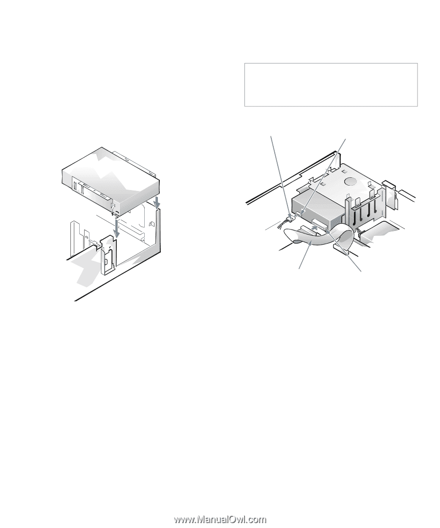
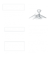
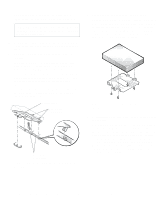
To ensure proper positioning of the drive in the chassis, insert and tighten all four screws in the order in which the holes are numbered (the holes are marked "1" through "4"). 6. Reinstall the drive/bracket assembly in the chassis. Align the notches on the front of the drive bracket (see Figure 7-8) with the front of the computer. Hold the bracket level, and lower the assembly straight down into place. Match the colored strip on the interface cable to the pin-1 end of the connector on the drive. CAUTION: You must match the colored strip on the cable with pin 1 on the drive's interface connector to avoid possible damage to your system. DC power cable power input connector Figure 7-9. Inserting the 5.25-Inch Drive/ Bracket Assembly Into the Drive Bay 7. If you are installing a drive that has its own controller card, install the controller card in an expansion slot. See "Installing an Expansion Card" in Chapter 6. 8. Connect a DC power cable to the power input connector on the back of the drive (see Figure 7-10). 9. Connect the interface cable in your upgrade kit to the interface connector on the back of the drive (see Figure 7-10). For a diskette drive or tape drive using the built-in diskette/tape drive interface controller, use the middle connector on the interface cable. interface cable interface connector Figure 7-10. Attaching Cables to a Drive in the 5.25-Inch Drive Bay 10. For an EIDE tape drive or CD-ROM drive, connect the other end of the interface cable to the interface connector labeled "IDE2" on the system board. For a drive that comes with its own controller card, connect the other end of the interface cable to the controller card. For a diskette drive or tape drive using the builtin diskette/tape drive interface controller, disconnect the interface cable from the connector labeled "DSKT" on the system board. Connect one end of the new interface cable to the DSKT connector on the system board. Check all cable connections. Fold cables out of the way to provide airflow for the fan and cooling vents. Installing Drives 7-5
-
 1
1 -
2
-
3
-
4
-
5
-
6
-
7
-
8
-
9
-
10
-
11
-
12
-
13
-
14
-
15
-
16
-
17
-
18
-
19
-
20
-
21
-
22
-
23
-
24
-
25
-
26
-
27
-
28
-
29
-
30
-
31
-
32
-
33
-
34
-
35
-
36
-
37
-
38
-
39
-
40
-
41
-
42
-
43
-
44
-
45
-
46
-
47
-
48
-
49
-
50
-
51
-
52
-
53
-
54
-
55
-
56
-
57
-
58
-
59
-
60
-
61
-
62
-
63
-
64
-
65
-
66
-
67
-
68
-
69
-
70
-
71
-
72
-
73
-
74
-
75
-
76
-
77
-
78
-
79
-
 80
80 -
 81
81 -
 82
82 -
 83
83 -
 84
84 -
 85
85 -
 86
86 -
 87
87 -
 88
88 -
 89
89 -
 90
90 -
91
-
92
-
93
-
94
-
95
-
96
-
97
-
98
-
99
-
100
-
101
-
102
-
103
-
104
-
105
-
106
-
107
-
108
-
109
-
110
-
111
-
112
-
113
-
114
-
115
-
116
-
117
-
118
-
119
-
120
-
121
 |
 |