Dell OptiPlex Gs Reference and Installation Guide (.pdf) - Page 76
Microprocessor Securing Clip, Removing the Microprocessor
 |
View all Dell OptiPlex Gs manuals
Add to My Manuals
Save this manual to your list of manuals |
Page 76 highlights
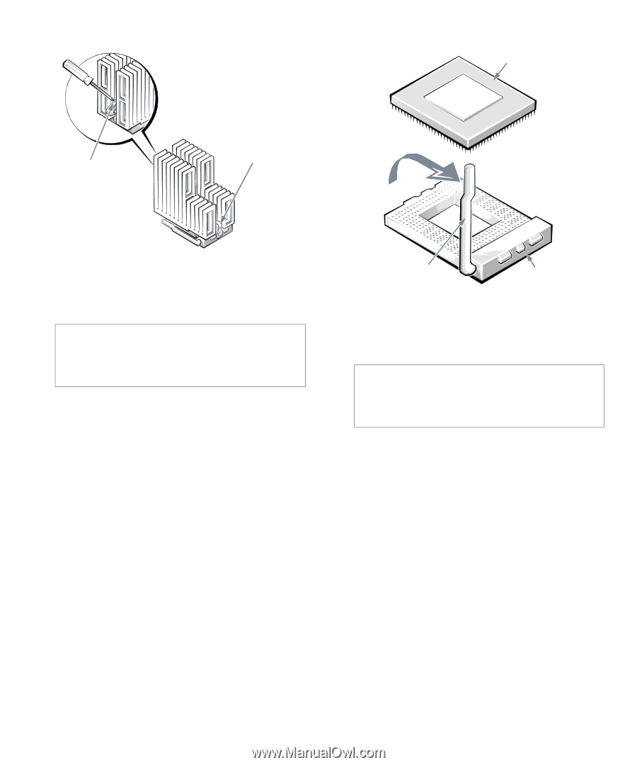
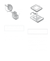
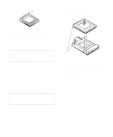
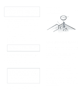
press here to release clip microprocessor securing clip hooks over tabs on left and right sides of socket microprocessor chip Figure 6-9. Microprocessor Securing Clip 4. Remove the microprocessor chip from the socket. CAUTION: Be careful not to bend any of the pins when removing the microprocessor chip from its socket. Bending the pins can permanently damage the microprocessor chip. Your microprocessor socket is a zero insertion force (ZIF) socket with a lever-type handle that secures the chip in, or releases it from, the socket. To remove the chip, pull the microprocessor-socket release lever straight up until the chip is released (see Figure 6-10). Then lift the chip out of the socket. Leave the release lever up so that the socket is ready for the new microprocessor. release lever microprocessor socket Figure 6-10. Removing the Microprocessor 5. Unpack the new microprocessor. CAUTION: Be careful not to bend any of the pins when unpacking the microprocessor. Bending the pins can permanently damage the microprocessor. If any of the pins on the chip appear to be bent, see the chapter titled "Getting Help" in your Diagnostics and Troubleshooting Guide for instructions on obtaining technical assistance. 6. Align the pin-1 corner of the microprocessor chip (see Figure 6-11) with the pin-1 corner of the microprocessor socket (see Figure 6-12). NOTE: Identifying the pin-1 corners is critical to positioning the chip correctly. Identify the pin-1 corner of the microprocessor by turning the chip over and locating the tiny gold finger that extends from one corner of the large central rectangular area. The gold finger points toward pin 1, which is also uniquely identified by a square pad. 6-8 Dell OptiPlex Gs and Gs+ Low-Profile Systems Reference and Installation Guide
-
 1
1 -
2
-
3
-
4
-
5
-
6
-
7
-
8
-
9
-
10
-
11
-
12
-
13
-
14
-
15
-
16
-
17
-
18
-
19
-
20
-
21
-
22
-
23
-
24
-
25
-
26
-
27
-
28
-
29
-
30
-
31
-
32
-
33
-
34
-
35
-
36
-
37
-
38
-
39
-
40
-
41
-
42
-
43
-
44
-
45
-
46
-
47
-
48
-
49
-
50
-
51
-
52
-
53
-
54
-
55
-
56
-
57
-
58
-
59
-
60
-
61
-
62
-
63
-
64
-
65
-
66
-
67
-
68
-
69
-
70
-
 71
71 -
 72
72 -
 73
73 -
 74
74 -
 75
75 -
 76
76 -
 77
77 -
 78
78 -
 79
79 -
 80
80 -
 81
81 -
82
-
83
-
84
-
85
-
86
-
87
-
88
-
89
-
90
-
91
-
92
-
93
-
94
-
95
-
96
-
97
-
98
-
99
-
100
-
101
-
102
-
103
-
104
-
105
-
106
-
107
-
108
-
109
-
110
-
111
-
112
-
113
-
114
-
115
-
116
-
117
-
118
-
119
-
120
-
121
 |
 |