Dell OptiPlex Gs Reference and Installation Guide (.pdf) - Page 82
Connecting Drives, Removing the Front-Panel Insert, for the 5-25-Inch Bay
 |
View all Dell OptiPlex Gs manuals
Add to My Manuals
Save this manual to your list of manuals |
Page 82 highlights
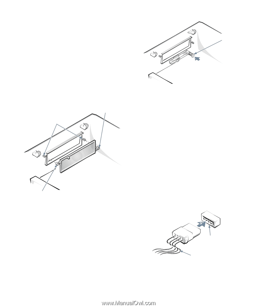
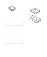
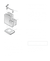
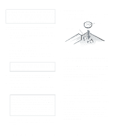
To remove the insert covering the 5.25-inch bay, follow these steps: 1. Turn off the system, including any attached peripherals, and disconnect all the alternating current (AC) power cables from their power sources. 2. Remove the computer cover as instructed in "Removing the Computer Cover" in Chapter 5. 3. Lay the computer cover upside down on a flat work surface, with the front of the cover facing toward you. 4. With your thumbs, press in each end of the insert until it snaps free of the cover (see Figure 7-2). computer cover (upside down) posts ring-tab eject button mechanism Figure 7-3. Removing the Front-Panel Insert for the 3.5-Inch Bay To replace the front-panel insert for the 5.25-inch bay, work from inside the cover. Position the insert behind the bay opening, insert the two ring-tabs (see Figure 7-2) over the posts on the inside of the opening, and firmly press both ends of the insert into place. To replace the front-panel insert for the 3.5-inch bay, work from outside the cover. Place the insert in position, and press it into the opening. ring-tab Figure 7-2. Removing the Front-Panel Insert for the 5-25-Inch Bay To remove the insert covering the 3.5-inch bay, follow these steps: 1. Complete steps 1 through 3 of the procedure for removing a 5.25-inch insert. 2. Inside the cover, locate the eject button mechanism for the 3.5-inch bay. Press the mechanism toward the front panel to snap the insert out of its opening. Connecting Drives When installing a drive, you connect two cables-a direct current (DC) power cable and an interface cable-to the back of the drive. Your drive's power input connector (to which you connect the DC power cable) resembles the connector shown in Figure 7-4. power input connector DC power cable Figure 7-4. DC Power Cable Connector 7-2 Dell OptiPlex Gs and Gs+ Low-Profile Systems Reference and Installation Guide
-
 1
1 -
2
-
3
-
4
-
5
-
6
-
7
-
8
-
9
-
10
-
11
-
12
-
13
-
14
-
15
-
16
-
17
-
18
-
19
-
20
-
21
-
22
-
23
-
24
-
25
-
26
-
27
-
28
-
29
-
30
-
31
-
32
-
33
-
34
-
35
-
36
-
37
-
38
-
39
-
40
-
41
-
42
-
43
-
44
-
45
-
46
-
47
-
48
-
49
-
50
-
51
-
52
-
53
-
54
-
55
-
56
-
57
-
58
-
59
-
60
-
61
-
62
-
63
-
64
-
65
-
66
-
67
-
68
-
69
-
70
-
71
-
72
-
73
-
74
-
75
-
76
-
 77
77 -
 78
78 -
 79
79 -
 80
80 -
 81
81 -
 82
82 -
 83
83 -
 84
84 -
 85
85 -
 86
86 -
 87
87 -
88
-
89
-
90
-
91
-
92
-
93
-
94
-
95
-
96
-
97
-
98
-
99
-
100
-
101
-
102
-
103
-
104
-
105
-
106
-
107
-
108
-
109
-
110
-
111
-
112
-
113
-
114
-
115
-
116
-
117
-
118
-
119
-
120
-
121
 |
 |